Environmental equipment, instruments and meters, robots, ...

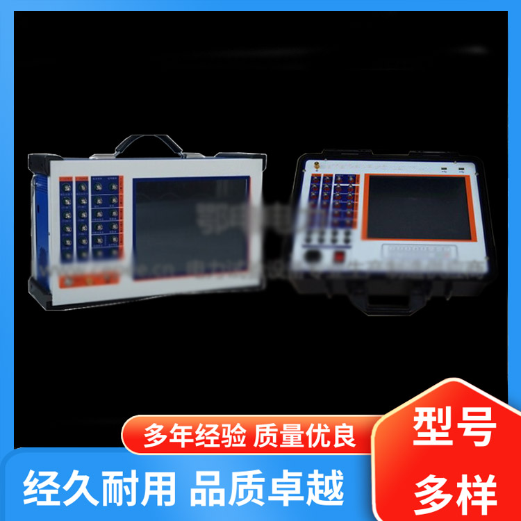
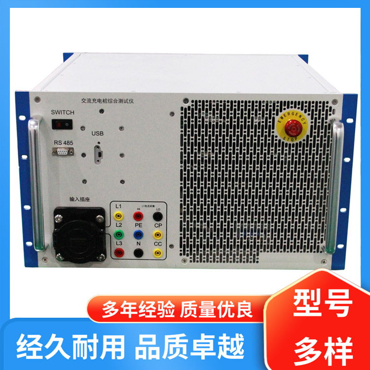
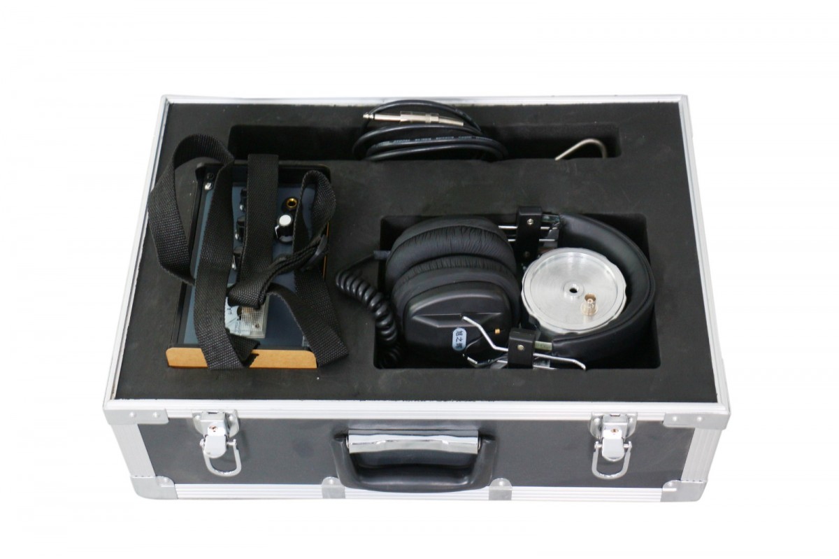
Cable path and positioning instruments are byThe DK-DGL transmitter, DK-DGD receiver, inductive probe, and potential difference detection frame make up this instrument. This specialized equipment is designed for cable and fiber optic fault location testing, suitable for various cables and fiber optics with metallic conductors (pairs, sheath, shielding). Its primary functions include locating ground insulation defects, detecting cable circuits, and testing cable burial depth, among others.
This instrument utilizes a quartz crystal oscillator and medium to large-scale integrated circuits. It features high reception sensitivity, low static drift, strong anti-interference capability, stable operation, and high accuracy. Due to the use of a small nickel-cadmium rechargeable battery for power supply, the instrument boasts compact size, light weight, low power consumption, and ease of portability, making it particularly suitable for fieldwork.
1. Principle of Routing Detection
When alternating current flows through a straight conductor, an axial alternating electromagnetic field is generated around it. Place a coil within this magnetic field, and an alternating voltage of the same frequency will be induced within the coil. The magnitude of the induced voltage depends on the position of the coil within the magnetic field. When the magnetic lines are parallel to the coil's axis, the induced voltage in the coil will be greater; when the coil's axis is perpendicular to the magnetic lines, the induced voltage will be greater. From this, the routing of the cable can be determined. Utilize the receiving coilThe 45° method can also determine the burial depth of underground cables.
2. Principle of Fault Detection Operation:
The direct current high-voltage pulses generated by the transmitter are sent into the cable under test, passing through poor insulation points to ground.
At the entry point, a point electric field is formed at the ground surface. The DC amplifier in the receiver is activated.
The potential difference probe measures the potential difference before and after the fault point (along the cable route). Due to the opposite signs of the potential difference before and after the fault point, when the front and rear order of the potential difference probe standar is unchanged, the central value indicator on the DC amplifier will swing in different directions. The direction of the central value indicator will change before and after the fault point. By observing the change in the swing direction of the indicator, the location of the cable-to-ground insulation fault can be determined. According to the principles of the electric field, the closer the receiver's potential difference probe standar is to the fault point, the greater the potential difference obtained under equal distance conditions; the greater the swing of the central value indicator; similarly, when the probe standar just leaves the fault point, the swing amplitude of the central value indicator is also large (but opposite in direction to the swing before crossing the fault point). If the fault point is exactly in the middle of the probe standar, due to the potential difference being zero, the swing amplitude of the central value indicator is also zero.


b2b.china9.net © Zhongshang 114 Hebei Network Technology Co., Ltd.Address: Room 6009, Oriental New World Center, No.118 East Zhongshan Road, Qiaoxi District, Shijiazhuang City, Hebei ProvincePlatform Service Hotline: 4006299930