Environmental equipment, instruments and meters, robots, ...

Executive Summary
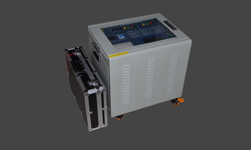
The Generator Comprehensive Parameter Tester is a highly integrated, feature-complete instrument.CPUSystem, consisting of three components80196 CPUComposition.
The Generator Comprehensive Parameter Tester has successfully completed primary tasks such as signal collection, calculation, display, and communication with the system. It also features a comprehensive self-check function. The Generator Comprehensive Parameter Tester employs precision12Please provide the Chinese content to be translated.A/DConverters, measurement accuracy all0.5Level above, some up to0.2Level, total measurable30Key electrical parameters of the generator.
The Generator Integrated Parameter Tester's ability to simultaneously measure these electrical parameters allows it to essentially complete the basic electrical start-up test functions, such as the auxiliary excitation no-load frequency characteristics, main excitation no-load test, main excitation load and generator short-circuit test, as well as the generator no-load test. It can also carry out tests such as generator frequency characteristics and synchronous grid connection. All test data are automatically recorded, with measurement results.Please provide the Chinese content to be translated into American English..Certainly!The complete curve is displayed dynamically during the excitation adjustment process, including curves for no-load and short-circuit tests. Some transient processes during the tests can be automatically captured, and the recording of these transient processes plays a crucial role in the analysis of the generator's characteristics.
Self-inspection feature
This unit is designed with an in-built self-check function for its main components, which can check the memory and communication buffer areas.A/DPerform self-inspection of interfaces, etc. (See operation instructions for details).
Measurement Principle
Measurement of general parameters such as voltage and current
Generator stator voltage, current, and rotor quantities are all processed by the channel processing circuit after being isolated from the input signal.A/DConverter, byCPUControl the sampling, processing, and calculation. The parameters of the main and auxiliary excitation stators can also be observed through waveforms, with a sampling interval of50No Chinese content provided./Cycle, observable short cycle2ms(Equal to500Hz)。
Measurement of the angle of function
The basic definition of power angle is: the time phase angle between the no-load electromotive force inside the generator and the terminal voltage. Another meaning refers to the two rotating magnetic fields (the no-load magnetic field of the rotor) between the stator and the rotor air gap during the operation of the generator.FdThe angle between the synthetic magnetic field (FS) in the air gap and the basic theory of synchronous motorsParkThe transformation formula leads to two conclusions:
ASecondary line voltage at the generator endUBCEach sine wave waveform's voltage vector direction corresponding to its rising zero crossing forms a fixed angle d with the vector direction of FS.iThis diDoes not change with the variation of the generator's operating conditions.
B、FdNo Chinese content provided. Please provide the text to be translated.dAxial direction, it is located at a fixed and unchanging position on the rotor radial, and we just need to find any point on the rotating rotor radial.dAxle fixed at an unchanging angle (with the corresponding angle set as)XoAxle). SodAxle & ThisXoThe angle of the shaft remains constant. Find or install a protrusion or indentation on a surface of the rotor (whether on the turbine side or the exciter side). Fix a magnetic resistance probe or eddy current probe at the corresponding stationary position. This probe can then be used to detect the rotor's movement during each cycle.XoA sharp pulse is generated at the shaft position. It is also possible to measure it by applying white paint to the rotor and utilizing the photoelectric conversion principle.
If no such signals are present, the speed signal of the rotor can be utilized; generally, this signal is generated with each revolution of the rotor.60A pulse, this signal is input into the instrument for waveform processing, then becomes a pulse quantity entering60Frequency Divider Circuit, the output can be identified asXoAxle.


b2b.china9.net © Zhongshang 114 Hebei Network Technology Co., Ltd.Address: Room 6009, Oriental New World Center, No.118 East Zhongshan Road, Qiaoxi District, Shijiazhuang City, Hebei ProvincePlatform Service Hotline: 4006299930