
Product Details
Pump and Valve Manufacturing Manufacturer
价 格Negotiable
最小起订1 An库存0 An
 Business Card
Negotiable

Negotiable

Negotiable

Negotiable
 Air Operated Valve Positioner, PJ
Negotiable
PJZX Pneumatic High-Pressure Angu
Negotiable
PJZJPW Pneumatic Bellows Control
Negotiable
Air Operated Valve Positioner, PJ
Negotiable
PJZX Pneumatic High-Pressure Angu
Negotiable
PJZJPW Pneumatic Bellows Control
Negotiable
 PJZN Pneumatic Double Seat Regula
Negotiable
PJZH Pneumatic Three-Way Control
Negotiable
PJZN Pneumatic Double Seat Regula
Negotiable
PJZH Pneumatic Three-Way Control
Negotiable
 PJZJPW Pneumatic Bellows Control
Negotiable
PJZJPW Pneumatic Bellows Control
Negotiable
 PJZJM Pneumatic Suction Sleeve Re
Negotiable
PJZJP Pneumatic Single Seat Regul
Negotiable
PJZJM Pneumatic Suction Sleeve Re
Negotiable
PJZJP Pneumatic Single Seat Regul
Negotiable
Abstract
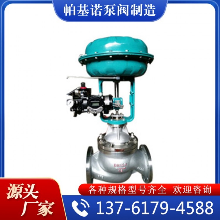
PJZF/H Type Pneumatic Diaphragm Three-way (Diverting/Merging) Control Valve utilizes a cylindrical thin-wall window-shaped valve core structure, differing from the sleeve-guided plunger-type valve core. Equipped with a multi-spring actuator, it offers advantages such as compact structure, light weight, small size, and easy assembly and disassembly.
Product Description
I. Overview
PJZF/H Type Pneumatic Diaphragm Three-Way (Splitting) Merging ValveAdjustable ValveUtilizing a cylindrical thin-walled window-shaped valve core structure, different from the sleeve guide of a plunger-type valve core. Equipped with a multi-spring actuator, it boasts advantages such as compact structure, lightweight, small size, and easy assembly and disassembly. Widely applied in controlling gases, liquids, steam, and other mediums, maintaining process parameters like pressure, flow rate, temperature, and liquid level at set values. Suitable for dividing one fluid into two outlets through a three-way valve or merging two fluids into one through a three-way valve. This series offers both three-way converging and diverging options. Nominal pressures include 1.6, 4.0, and 6.4 MPa; valve body sizes range from DN25 to DN200. Fluid temperatures range from -60°C to +450°C. Flow characteristics are linear and parabolic.
II. Features
The valve core is in the open position for both flow directions, ensuring stable operation of the valve. In addition to the sleeve guidance at the upper valve cover, the side of the valve core also provides guidance against the inner surface of the valve seat, with a large guided area for reliable performance. The actuator uses a multi-spring structure, reducing the height by 30% and the weight by 30%.
Section 3: Main Component Materials
Body and Cover: HT200, ZG230-450, ZG1Cr18Ni9Ti
Valve core and seat: 1Cr18Ni9Ti, Stellite alloy surfacing.
Wavy diaphragm: Nitrile rubber reinforced with polyester fabric;
Filler: PTFE, Flexible Graphite
Film Cover: A3; Spring: 60SiMn
Valves and Push Rods: 2Cr13, 1Cr18Ni9Ti
Socket: 2Cr13
Soft Seated Valve Core: Enhanced PTFE
Gaskets: Rubber asbestos board, 10, 1Cr18Ni9Ti asbestos wrapped gaskets.
IV. Technical Specifications
Nominal Pipe Size DN (mm) | 25 | 32 | 40 | 50 | 65 | 80 | 100 | 125 | 150 | 200 | ||
| Rated Flow Coefficient (KV) | Confluence | 8.5 | 13 | 21 | 34 | 53 | 85 | 135 | 210 | 340 | 535 | |
| Divert | 8.5 | 13 | 21 | 34 | 53 | |||||||
| Rated Stroke L (mm) | 16 | 25 | 40 | 60 | ||||||||
| Effective Diaphragm Area Ae (cm²) | 280 | 400 | 600 | 1000 | ||||||||
| Nominal Pressure PN (MPa) | 1.6、4.0、6.4 | |||||||||||
| Intrinsic traffic characteristics | Straight, Parabolic | |||||||||||
| Inherent adjustable ratio (R) | 30 | |||||||||||
| Operating Temperature t (°C) | Standard Type: Cast Iron - 20~200, Cast Steel - 40~250, Cast Stainless Steel - 60~250 Thermal Dissipation: Cast Steel -40~450; Cast Stainless Steel -60~450 | |||||||||||
| Two medium temperature differences t (°C) | Cast Iron ≤150, Cast Steel, Cast Stainless Steel ≤200 | |||||||||||
| Signal Range Pr (kPa) | 40~200 | |||||||||||
| Gas Source Pressure Ps (MPa) | 0.14~0.4 | |||||||||||
| Permitted leakage rate (l/h) | 10-4×Rated Valve Capacity | |||||||||||
| Allowable pressure difference △P (MPa) | 0.86 | 0.75 | 0.48 | 0.31 | 0.27 | 0.18 | 0.11 | 0.12 | 0.09 | 0.05 | ||
V. Dimensions

| Nominal Bore Size | 25 | 32 | 40 | 50 | 65 | 80 | 100 | 125 | 150 | 200 | ||
| A | 282 | 306 | 306 | 306 | 394 | 394 | 394 | 498 | 498 | 498 | ||
| H1 | PN16 | 121 | 130 | 140 | 153 | 178 | 190 | 200 | 260 | 320 | 360 | |
| PN40 | 130 | 140 | 150 | 160 | 185 | 200 | 220 | 280 | 320 | 380 | ||
| PN64 | 160 | 170 | 180 | 200 | 230 | 250 | 282 | 310 | 430 | 480 | ||
| H | Please provide the Chinese content to be translated. Transmit Type | PN16/PN40 | 490 | 480 | 540 | 580 | 710 | 730 | 750 | 895 | 1005 | 1045 |
| PN64 | 560 | 561 | 596 | 630 | 760 | 798 | 876 | 892 | 1200 | 1263 | ||
| High Temperature Type | 600 | 615 | 650 | 670 | 850 | 870 | 900 | 1040 | 1330 | 1370 | ||
| Heavy Quantity (kg) | 普 Available for export Model | PN16 PN40 | 21 | 23 | 33 | 36 | 64 | 72 | 92 | 155 | 193 | 286 |
| PN64 | 25 | 28 | 40 | 45 | 74 | 85 | 112 | 180 | 243 | 336 | ||
| High-Temperature Type | Weight Increase (5~10)% | |||||||||||
Section 6: Performance Specifications
Item | Index value | Item | Index Value | ||||
| Basic Error % | Without GPS tracker | ±5.0 | Always Point Deviation % | Air Valve | No GPS tracker | Starting Point | ±5.0 |
| With GPS tracker | ±1.0 | End Point | ±2.5 | ||||
| Difference Return % | No GPS Tracker | ≤3.0 | With locator | Starting Point | ±1.0 | ||
| Tracker-equipped | ≤1.0 | End Point | ±1.0 | ||||
| Gas valve | No GPS Tracker | Origin | ±2.5 | ||||
| End Point | ±5.0 | ||||||
| Dead Zone % | Without GPS tracker | ≤3.0 | With locator | Origin | ±1.0 | ||
| End Point | ±1.0 | ||||||
| With locator | ≤0.4 | Permit leakage L/h | 0.002 x valve rated flow | ||||
| Rated Stroke Deviation % | ±2.5 | ||||||
Section 7: Allowable Pressure Difference
| Switching Method | Execution Machine Model No. | Spring Range Kpa | Gas Pressure Kpa | Please provide the attachment. | Nominal Bore Size | ||||||||
| 20 | 25 | 40 | 50 | 65 | 80 | 100 | 150 | 200 | |||||
| Gas Valve | ZHA-22 | 20-100 20-100 40-200 | 0.14 0.25 0.40 | - P P or R | 3.0 6.4 6.4 | 3.0 6.4 6.4 | |||||||
| ZHA-23 | 20-100 20-100 40-200 | 0.14 0.25 0.40 | - P P or R | 2.25 6.4 6.4 | 1.95 6.4 6.4 | ||||||||
| ZHA-34 | 20-100 20-100 40-200 | 0.14 0.25 0.40 | - P P or R | 2.36 6.4 6.4 | 2.04 6.4 6.4 | 1.67 6.4 6.4 | |||||||
| ZHA-45 | 20-100 20-100 40-200 | 0.14 0.25 0.40 | - P P or R | 1.41 6.4 6.4 | 1.41 6.4 6.4 | ||||||||
| Air Valve | ZHB-22 | 20-100 40-200 80-240 | 0.14 0.25 0.40 | - P or R P | 1.5 4.5 6.4 | 1.5 4.5 6.4 | |||||||
| ZHB-23 | 20-100 40-200 80-240 | 0.14 0.25 0.40 | - P or R P | 1.13 3.38 6.4 | 0.98 2.93 6.4 | ||||||||
| ZHB-34 | 20-100 40-200 80-240 | 0.14 0.25 0.40 | - P or R P | 1.18 3.54 6.4 | 1.02 3.06 6.4 | 0.84 2.51 5.85 | |||||||
| ZHB-45 | 20-100 40-200 80-240 | 0.14 0.25 0.40 | - P or R P | 0.71 2.12 4.94 | 0.57 2.12 4.94 | ||||||||
Note: 1> P—indicates valve positioner; R—indicates relay; 2> The allowable pressure difference is the maximum value of ∆P when the valve is closed at P2=0.
3. Differential pressure over 1.0 Ma, valve plug and sleeve surface surfacing with hard alloy; 4. Optional accessories: positioners, handwheel assemblies, air filter regulators, etc.
Section 8: Order Instructions
1. Product Model 2. Nominal Pressure 3. Nominal Bore Size 4. Flow Coefficient Kv 5. Flow Characteristics
6. Valve Operation; 7. Medium Working Temperature; 8. Ambient Temperature; 9. Signal Pressure (Spring Range)
10. Valve body and valve seat materials; 11. Other special requirements;

Phone Consultation