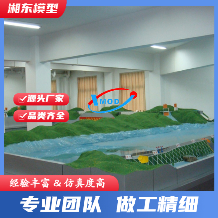


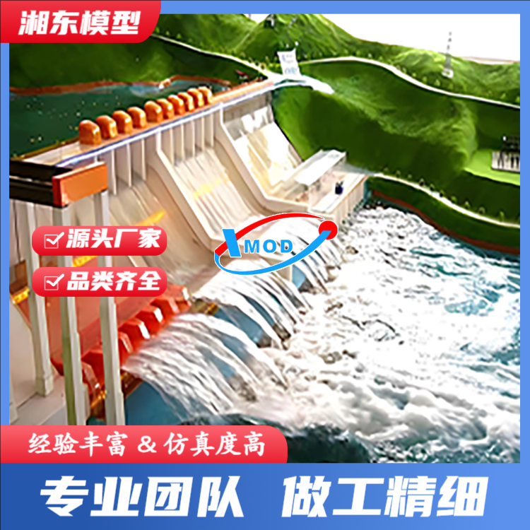


Hydro turbine models refer to scaled-down, transparent models of the water flow components of the actual turbine, including the full-transparent spiral casing and tailrace, designed to mimic the real turbine's hydraulic performance. These models clearly demonstrate, through observation and testing of the scaled-down turbine, the cavitation performance of the turbine's runner, among other characteristics.
Part 1: Model Production Section:
1. Pressure管道, made from fully transparent acrylic glass through high-temperature molding, with special waterproofing treatment.
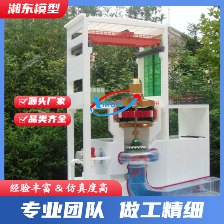
2. Generators made of green transparent acrylic, clearly showcasing the generator's rotor, stator, ventilation and cooling system, etc.
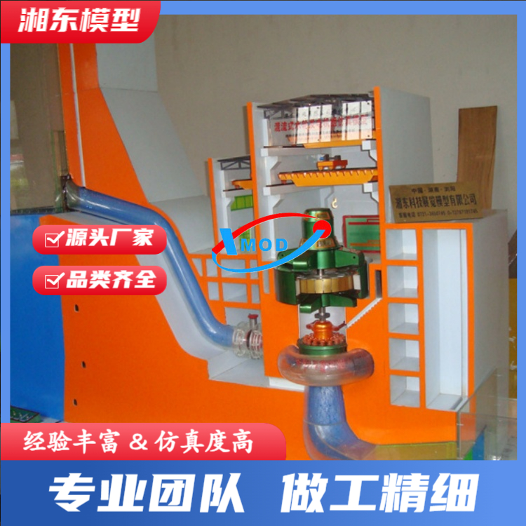
3. Shell made of fully transparent acrylic, the shell is pressure-resistant and can withstand the impact of natural water flow up to 10 meters. It is suitable for teaching and practical training experiments. The fully transparent shell allows for a clear display of fixed guide vanes, moving guide vanes, and the turbine (its working state can be clearly shown through the water flow).
4. Tail pipe, made from fully transparent polycarbonate through high-temperature molding with special waterproofing process.
Part Two: Control Section:
Manual/Controlled, operated through corresponding buttons to control the recirculation pump, upstream gates, and movable guide vanes, etc., to automatically control the upstream water level.
2. DCS supervisory control, monitoring factors such as reservoir level, pressure, flow rate, and turbine speed via the supervisory computer.
Hydro Turbine Model Manufacturer - Mixed Flow Turbine Generator Set Simulation Model - Hydro Turbine Experimental Testing Equipment
The most prominent feature of the model is the all-transparent, pressure-resistant casing, which is made using a special process.
This helical casing successfully resolves the two major contradictions of conventional helical casings, which cannot withstand pressure for simulation demonstrations and are not convenient for teaching or experiments due to their metallic nature, thereby establishing a reputation as the leader among peers. Our company has manufactured this for the North China Institute of Water Resources.
The postgraduate project "Reversible Model of Visual Turbine Generator," is termed "A First in China."
I. Basic Structure
Engineered assembly (models crafted to a 1:8 scale with actual dimensions)
Housing. Full transparent, integral pressure-resistant housing with special process seams, capable of preventing future adhesive separation and cracking.
The hassle, capable of withstanding water head impacts over 20 meters, and offering a panoramic view of the operation of each component from all angles.
Dynamic features: such as fixed guide vanes with light colors, transparent or semi-transparent movable guide vanes, and turning vanes made of copper sheets.
Wheel, dark butterfly valves, etc. - sizes, shapes, positions, functions, operating states, and water flow conditions
The condition is clear at a glance. Corrosion and moisture-resistant, strong and durable. In summary, this shell successfully resolves the conventional issues.
Several contradictions, such as the shell's inability to withstand pressure for simulation demonstrations and the inconvenience of the metal shell for teaching.
And regarded as the leader among peers.
Flywheel. The blades of the flywheel are formed by stamping copper sheets, with their size and shape proportionally reduced.
Seated, it is tightly integrated with the upper and lower seats to form an integral unit, capable of high-speed operation under hydraulic impact, with the upper section...
Stainless steel shaft connects with the generator section, offering both durability and rust resistance.
Activity guide vanes and regulators. Streamlined guide vanes are available in transparent and opaque versions, produced in batches.
Uniform in appearance, allowing for flexible adjustment and a tight closure. The regulating mechanism is lifelike, available in manual and electric versions.
Two options available, can be chosen individually or combined.
Generator. The main shaft of the generator is equipped with a small generator for actual power generation demonstration; lifting and lowering mechanism
Made of transparent material, viewable directly; stator and rotor仿实体制成,with added colors, square
For explanation purposes; there are 60 in the stator section. The section can be easily disassembled at any time, convenient for teaching; adjustable speed, with electric lights, etc.
The indicator is clearly visible. The entire structure is supported by a stainless steel frame, making it easy to observe.
Attached facilities. Includes sectioned factory structure, operating cranes, transparent tailwater pipes, door opening machines, etc.
Yes
Base. Framed with wooden planks, covered with nine-ply board and then new materials are applied on top, with stainless steel corners.
Overall smooth and sturdy, corrosion and moisture-resistant.
2. Recirculating Water Supply (Head height determined according to customer's needs)
Recirculating water supply, equipped with three tanks: the upper tank, lower tank, and tail tank; interconnected by feed water.
PVC pipes are interconnected, with large-diameter submersible pumps used for water level elevation.
Three water tanks are all sized based on theoretical calculations and verified through experiments. The upper water tank (rep)
The upstream water level) and the downstream water tank) are made of new materials and reinforced with angle steel externally, which can prevent deformation.
Form cracks; The overhead water tank is supported by a tower-like frame made of angle iron (removable) and internally fitted with valves for opening and closing.
Operated on the ground, the tail water tank (representing downstream water level) is slightly formed from reinforced transparent organic sheets, with stainless steel frames for reinforcement.
Harmonious and aesthetically pleasing.
Section 2: Water Permeability Test
This product is a large-scale dynamic simulation model, capable of actual water circulation experiments, demonstrating the gold process as it is in real life.
The hydropower generating set operates in perfect alignment with the power generation process. During the experiment, simply press the power button to start filling the upper water tank.
Turn the water tank valve to start the power generation demonstration. Students can directly observe the various components of the water turbine generator set.
Shape and dynamics, the fork can be observed to show the state of water flow through each part. Because it can truly emit
Electricity arrives with high reliability. A powerful assistant for teaching and a reliable instrument for experimental research.
Our company can also customize simulation models of impulse water turbine generator sets, bulb turbine generator sets, and axial flow water turbine generator plants.
Riverbed-type hydropower units, Mixed-flow turbine generators, Bubble through-flow power generation units, Water bucket turbine generator simulation models,
Axial Flow Turbine Generator Set Model
Turbine Model - Axial Flow, Turbine Model - Impulse Flow, Sales Manufacturer Phone Number
During the operation of the turbine model, guide vanes must be adjusted in accordance with the load, while the runner rotates and adjusts the blade angle to maintain a good coordination with the guide vanes, which is referred to as "dual regulation." This ensures that the turbine maintains a high efficiency over a wide range of output.
Tilted Flow Turbine Model: The transparent PMMA casing, inclined in arrangement, is fixed on the seat ring. The twelve seat ring pillars are inclined at 35° to the horizontal line. The inclined guide vane mechanism with a 45° angle consists of twenty-four guide vanes, a guide vane drive mechanism, the turbine top cover, and the guide vane bottom ring. The guide vanes with a double support structure have symmetrical airfoils varying in height. The guide vane bearings are wooden bushes, lubricated automatically by water passing through. To prevent water leakage, a rubber bowl is fitted on the upper shaft neck. The guide vane drive mechanism is composed of a crank arm, a connecting rod connected to the crank arm with a ball pivot, and a control ring connected to the connecting rod with a ball pivot. The hinge of the control ring is connected to two annular impellers.
The runner blades of the runner-type water turbine model can automatically adjust their angle of placement according to the operating conditions, matching the opening degree of the guide vane. To rotate the blades, the runner body is equipped with pistons, cylinders, piston rods, operating frames, connecting rods, and cranks, etc. The upper part is connected to the main shaft with a pressure oil pipe, while the lower part is fixed with a drain cone. Most of the main shafts are horizontally arranged, with a few being inclined.
Axial flow turbine model, a horizontal shaft turbine model where the water flows primarily along the horizontal axis within the channel. It is mainly suitable for heads of 1 to 25 meters and is a type of low-head, high-flow hydroelectric power station model. Due to the water flowing primarily along the axis without turning, the turbine's water passage capacity and hydraulic efficiency can be enhanced. Particularly suitable for tidal power station models, its features such as bidirectional power generation, bidirectional water pumping, and bidirectional water draining are ideal for comprehensive utilization of low-head hydraulic resources.
Axial flow turbine wheels can be categorized into two types: fixed-paddle and variable-paddle. The main difference lies in the variable-paddle wheel's ability to automatically adjust the blade angle in response to changes in guide vane opening and head, maintaining a good co-relationship with the guide vanes. During the operation of the turbine, the guide vanes must be adjusted according to the load. The wheel, while rotating, adjusts the blade angle to maintain a good co-relationship with the guide vanes, known as "dual regulation." This ensures the turbine maintains high efficiency over a wide range of output. Fixed-paddle wheels, however, cannot adjust the blade angle during operation. When the unit load changes and the guide vane opening is altered, the blade angle cannot be adjusted promptly, leading to water flow impacting the blades. As a result, the turbine's efficiency range is narrow across the entire output spectrum. Despite this, their simple structure makes them still widely used in small and medium-sized power stations.
We consistently adhere to the business philosophy of "customer first, excellence in all," committed to providing swift and comprehensive services. While perfecting product quality, we always prioritize excellent customer service as the key to winning the market. Our technical staff are available for timely service in any region.