
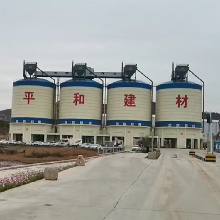


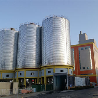
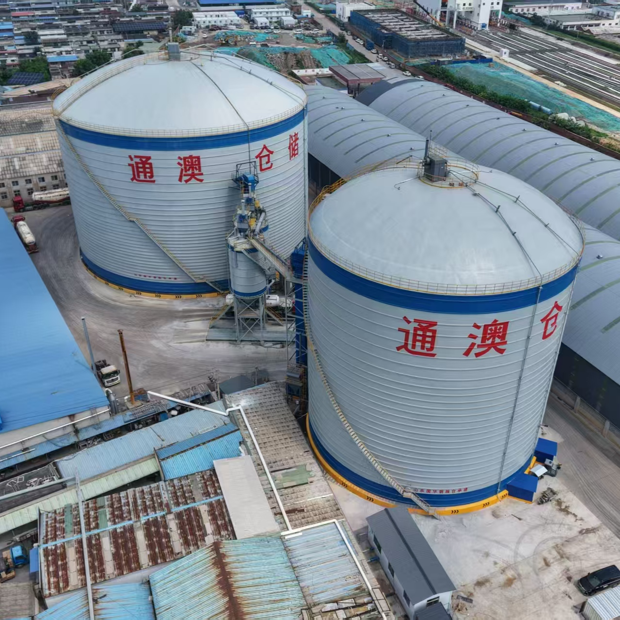
The construction process for fly ash steel silos covers multiple stages, including design, foundation treatment, preparation of materials and equipment, main construction, corrosion and sealing treatment, installation of supporting facilities, and acceptance and maintenance. It requires strict control of technical parameters and safety standards, as detailed below:
I. Construction Preparation and Foundation Treatment
Design Review and Technical Briefing
The technical team will review the storage body dimensions, node construction, and material specifications to ensure the design parameters meet the requirements for fly ash stacking density (0.6-1.0t/m³) and repose angle (35°-45°).
Reserve a safety factor of 10%-15% to accommodate fluctuations in lateral pressure caused by variations in material moisture content.
Prepare construction technical handover documents, specifying welding process parameters, corrosion coating thickness, and other critical indicators.
Geological Survey and Foundation Treatment
Utilize geological radar scanning technology to identify site geological structures, and reinforce the soft soil foundation areas.
Design features 800mm diameter CFG piles, 18 meters in length, with a spacing of 1.5 meters, arranged in a plum blossom pattern. This ensures a ground bearing capacity of ≥150kPa and differential settlement of ≤5mm.
After foundation treatment, static load tests and low strain detections are conducted, with a requirement for a 100% pass rate.
II. Material Procurement and Equipment Configuration
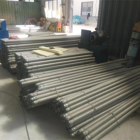
Steel and Welding Materials
The main structure is made of Q355B weather-resistant steel plate, with thickness determined by the height of the storage body in sections (bottom: 3-4mm, middle: 2.5-3mm, top: 2-2.5mm).
Welding materials utilize E5015 welding rods with CO₂ gas shielded welding, and the welding wire is selected as ER50-6, with a diameter of 1.2mm.
Corrosion and sealing materials
Corrosion-resistant coating: Epoxy zinc-rich primer (dry film thickness 80μm), glass flake finish coat (dry film thickness 200μm).
Sealants: Polysulfide sealant and三元乙丙橡胶seal strips.
Construction Equipment
Equipped with 500-ton crawler cranes, coil slitting machines, automatic welding robots, sandblasting and rust removal equipment, ultrasonic flaw detectors, laser alignment instruments, etc., all equipment must be inspected prior to entry.
III. Main Structure Construction
Basic Construction
Excavation depth of the foundation pit is determined based on geological conditions (usually 3-4 meters), with the slope gradient set at 1:0.5. Drainage and water cutoff ditches are installed at the top of the slope.
Upon base acceptance, lay a 300mm thick graded sand and gravel bedding layer, compacted in layers to achieve a compaction factor of ≥0.96.
Pour a 100mm thick C15 concrete base with a surface flatness tolerance of ≤±5mm.
The circular foundation is constructed with C30 reinforced concrete, featuring a trapezoidal cross-section (top width 1.2 meters, bottom width 2.0 meters, height 1.5 meters). The reinforcement spacing is 150mm, and a double-layer, bidirectional reinforcement mesh is installed.
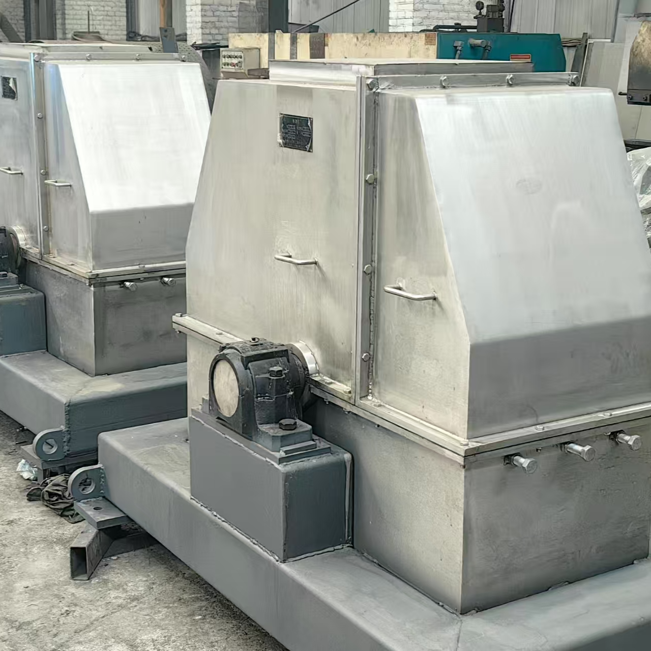
Warehouse body installation
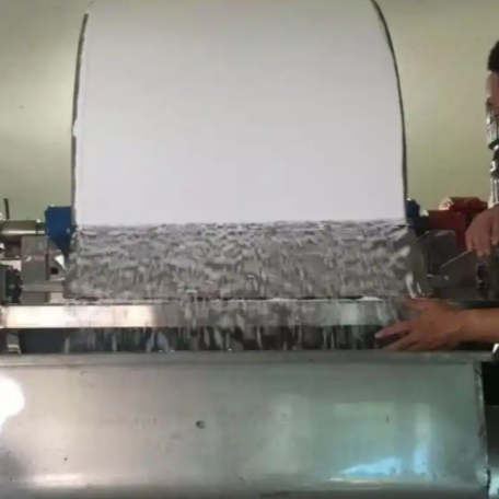
Coil Processing: Processed on-site with CNC coil rolling machines to produce corrugated steel sheets, with a curvature radius deviation of ≤±50mm.
Lifting Process: Divide the storage body into 6-8 lifting sections, utilizing 500-ton crawler crane modular lifting. Each section's steel plate pre-assembly error is controlled within ±10mm in diameter, ±30mm in circumference, and ≤15mm in diagonal deviation.
Verticality Calibration: Perform a verticality calibration after installing every 3 layers of steel plates. The overall verticality deviation should be ≤ H/1000 (where H is the height of the storage body) and ≤ 50mm.
Connection Method: High-tensile bolted joints (10.9 grade friction bolts, torque coefficient 0.11-0.15) combined with welding, utilizing TIG welding for root pass (3mm) and CO₂ gas shielded welding for filling and covering.
Four: Anti-corrosion and Sealing Treatment
Surface Treatment
The steel plate surface is blast cleaned to Sa2.5 standard, with a surface roughness of 50-80μm. The priming is completed within 4 hours after rust removal.
Coating Application
Primer: Epoxy zinc-rich primer (dry film thickness 80μm, high-pressure airless spray in two coats).
Intermediate Paint: Epoxy iron oxide intermediate paint (dry film thickness 120μm, one coat).
Face Paint: Glass flake face paint (dry film thickness 200μm, applied in 2 coats), thickness inspection is conducted after each coat is applied.
Sealing Treatment
EPDM rubber seals are installed at the bolted joint, and polythiophene sealant is applied on both sides of the weld.
Fifth, installation of supporting facilities
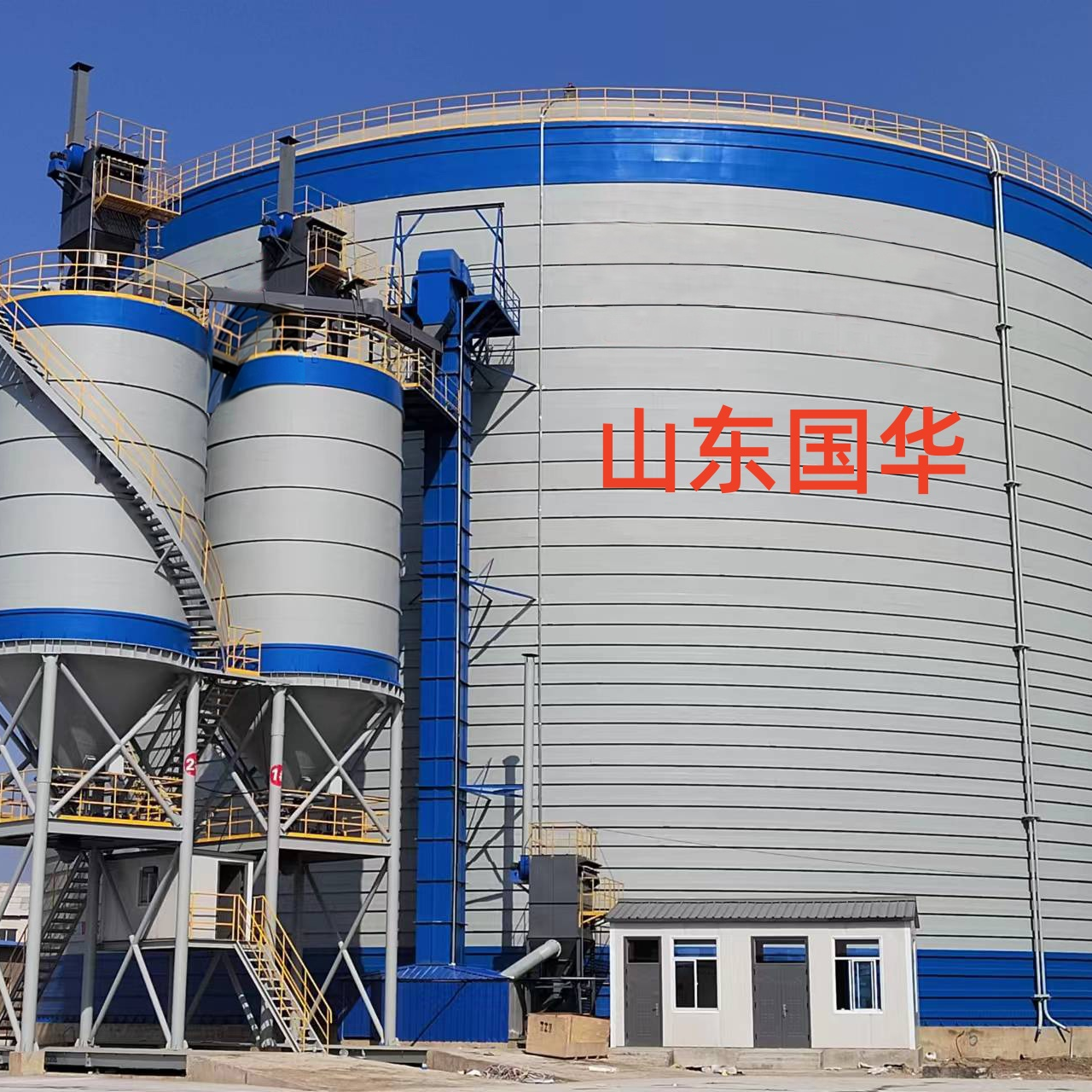
Structure at the top and bottom of the warehouse
Top of the silo: Conical steel structure roof (slope 1:5), composed of a central annular beam (Φ325×8mm seamless steel tube), radial beams (H-beam H200×100×5.5×8), and color steel plates (0.6mm thick galvanized aluminum zinc plate).
Bin Bottom: Inverted conical structure (slope 5°), lined with 6mm thick patterned steel plate, featuring a conical discharge port (diameter 800mm) at the center, equipped with an electric discharge valve, and surrounded by a circular drainage channel (channel width 200mm, slope 0.5%).
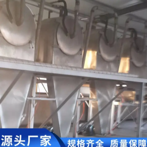
Ventilation and dust removal system
Top of silo equipped with pulse jet bag filter (handling air volume 10,000 m³/h, filtering area 200 m²), exhaust pipe diameter 300mm, with rain hat and fire damper.
The lower section of the storage body is equipped with 4 intake ports, featuring louvers and filters.
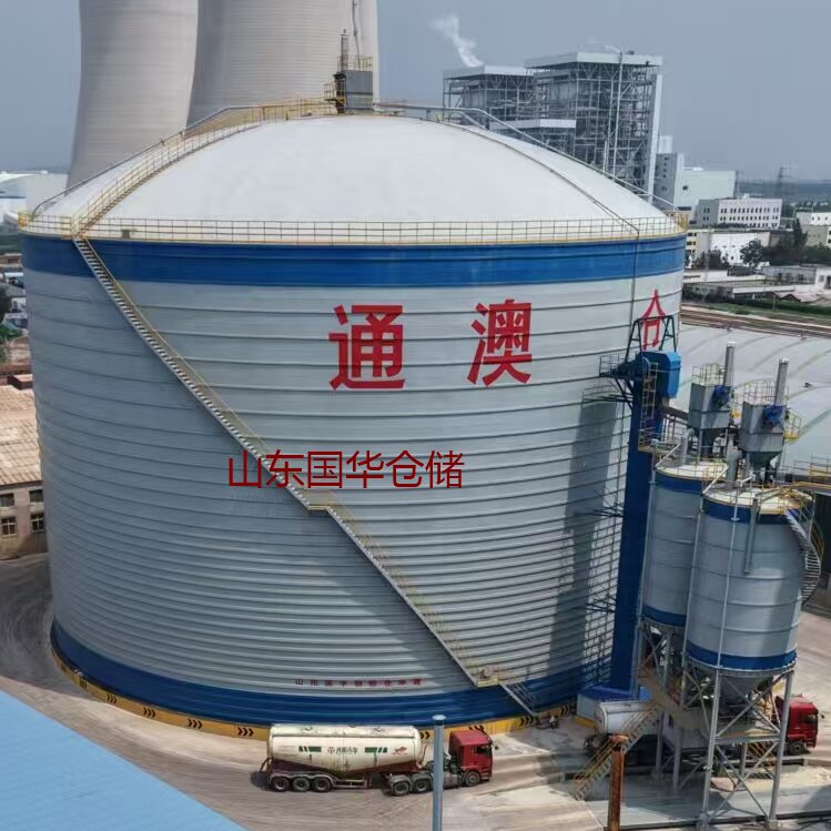
Raw Material and Output Material Systems
Feeding System: pneumatic conveying method, 2 DN200mm conveying pipelines, Roots blower for air supply (air pressure 50kPa, air volume 20m³/min), equipped with 4 feeding ports at the top of the silo.
Material Discharge System: Equipped with 6 unloading zones at the warehouse bottom, each zone is fitted with an pneumatic unloading valve and a screw conveyor. Sequential unloading is achieved through a PLC control system, with an emptying rate of ≥95%.
VI. Inspection and Maintenance
Quality Acceptance
Each weld undergoes 100% visual inspection and 20% non-destructive testing (UT/MT), with an pass rate of ≥98%.
Upon completion of the basic construction, set up settlement observation points and regularly monitor settlement data.
Post-maintenance
Regularly inspect the stability of the storage structure, control the height of material stacking, and avoid excessive lateral pressure causing deformation of the storage body.
Establish a stock liquidation system, conducting a thorough stock-out every 6 months and inspecting the unloading port condition.
Add temperature and humidity sensors, material level radar, and stress monitoring devices to achieve real-time data collection and early warning.