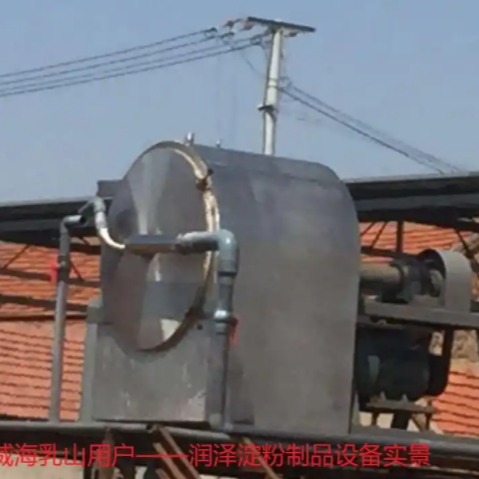


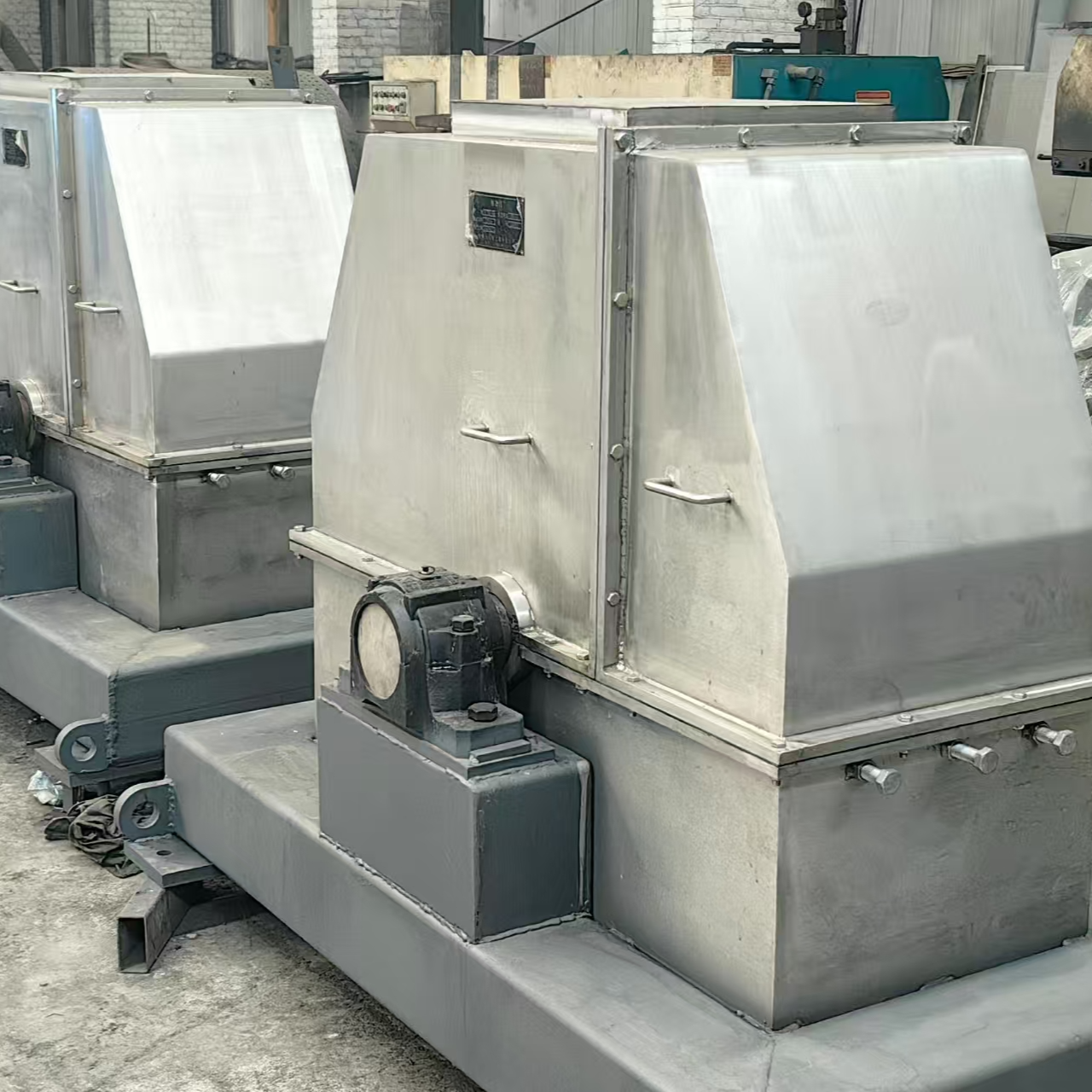


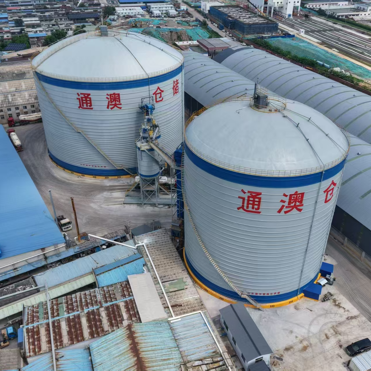
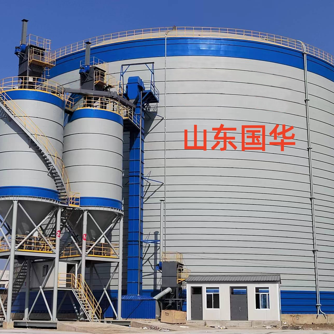
Fluidizing rods, also known as gasification tubes or gasification rods, are a crucial device in steel silo storage systems for improving material flow. By injecting compressed air into the material within the silo, the material achieves a fluid-like state, thereby solving issues such as caking, bridging, and blockages that occur during storage of powdered or granular materials. The following outlines the core functions and technical principles of fluidizing rods in steel silo storage:
I. Core Function
Prevent material from caking and bridging
Background of the Issue: Fly ash, cement, mineral powder, and other materials are prone to caking due to humidity, pressure, or prolonged static storage, leading to "bridging" phenomena that cause blockages at the discharge outlet.
Fluidized Bed Solution: Injects compressed air (pressure 0.2-0.5 MPa) into the material layer through evenly distributed pores, causing relative movement between material particles, breaking up agglomerations, and forming a "fluidized" layer to ensure smooth material flow.
Enhance material dispatch efficiency
Traditional issue: Bottom materials in steel silos are compacted by gravity, resulting in poor flowability. Discharging requires reliance on vibrators or manual breaking of arches, which is inefficient and prone to damaging the silo.
Flotation Rod Advantages: After installing the flotation rod at the bottom of the storage, air penetrates from the bottom upwards, causing the material to suspend and appear in a "boiling" state, reducing friction, and increasing the discharge speed by 30%-50%, without the need for additional mechanical de-clogging.
Uniform unloading and reduced residue
Uniformity: The fluidizing rods are arranged in a circular or grid pattern to ensure simultaneous fluidization of materials in all areas of the storage, avoiding localized accumulation or uneven unloading.
Residual Control: The fluidization action ensures complete loosening of the material at the bottom of the silo, achieving an unloading rate of over 95%, thereby minimizing material residuals and waste.
Reduce energy consumption and maintenance costs
Energy consumption comparison: Traditional vibration systems have higher power requirements (e.g., 5-10kW), while fluidizing rods only require compressed air (power around 0.75-2.2kW), reducing energy consumption by 60%-80%.
Maintenance Simplification: The fluidizing rod has no mechanical moving parts, resulting in a low failure rate and extending the maintenance cycle to 3-5 years, with maintenance costs reduced by over 50%.
Section II: Technical Principles and Structural Features
Operating Principle
Fluidization Process: Compressed air is uniformly released through the micropores of the fluidizing rods (pore size 0.1-0.5mm), forming bubbles in the material layer. As the bubbles rise, they carry the particles, giving the material a fluid-like mobility.
Critical Flow Rate: Calculated based on material characteristics (such as particle size, density) to determine the minimum fluidization velocity (usually 0.1-0.3 m/s), ensuring air flow can break up agglomerations without dispersing the material.
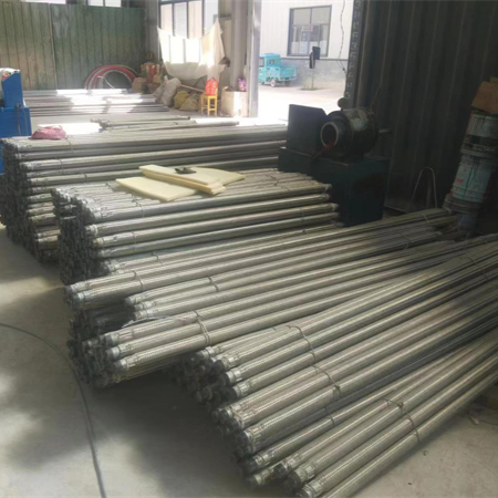
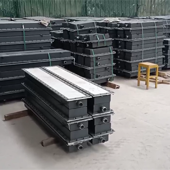
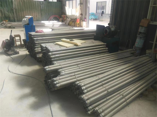
Structural Composition
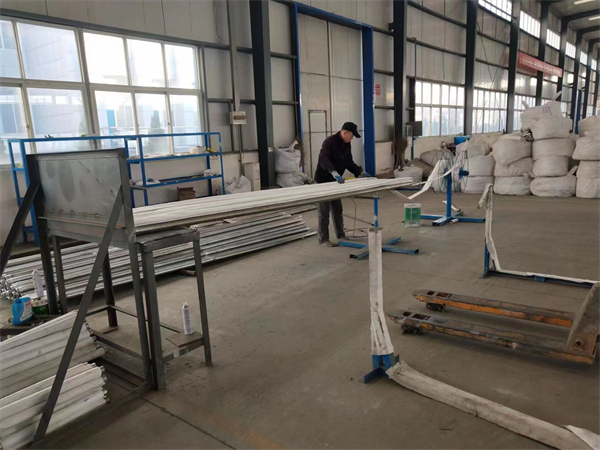
Tube Material: Galvanized steel pipe or stainless steel pipe (diameter 50-100mm), highly corrosion-resistant, with a service life of over 10 years.
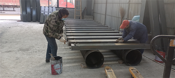
Permeable layer: Wrapped with multiple layers of sintered metal mesh or high polymer filter cloth (pores 0.02-0.1mm) around the pipe wall to prevent material from entering and blocking the air holes.
Connection Method: Connected via quick couplings to compressed air pipelines for easy installation and replacement.
Arrangement style
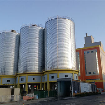
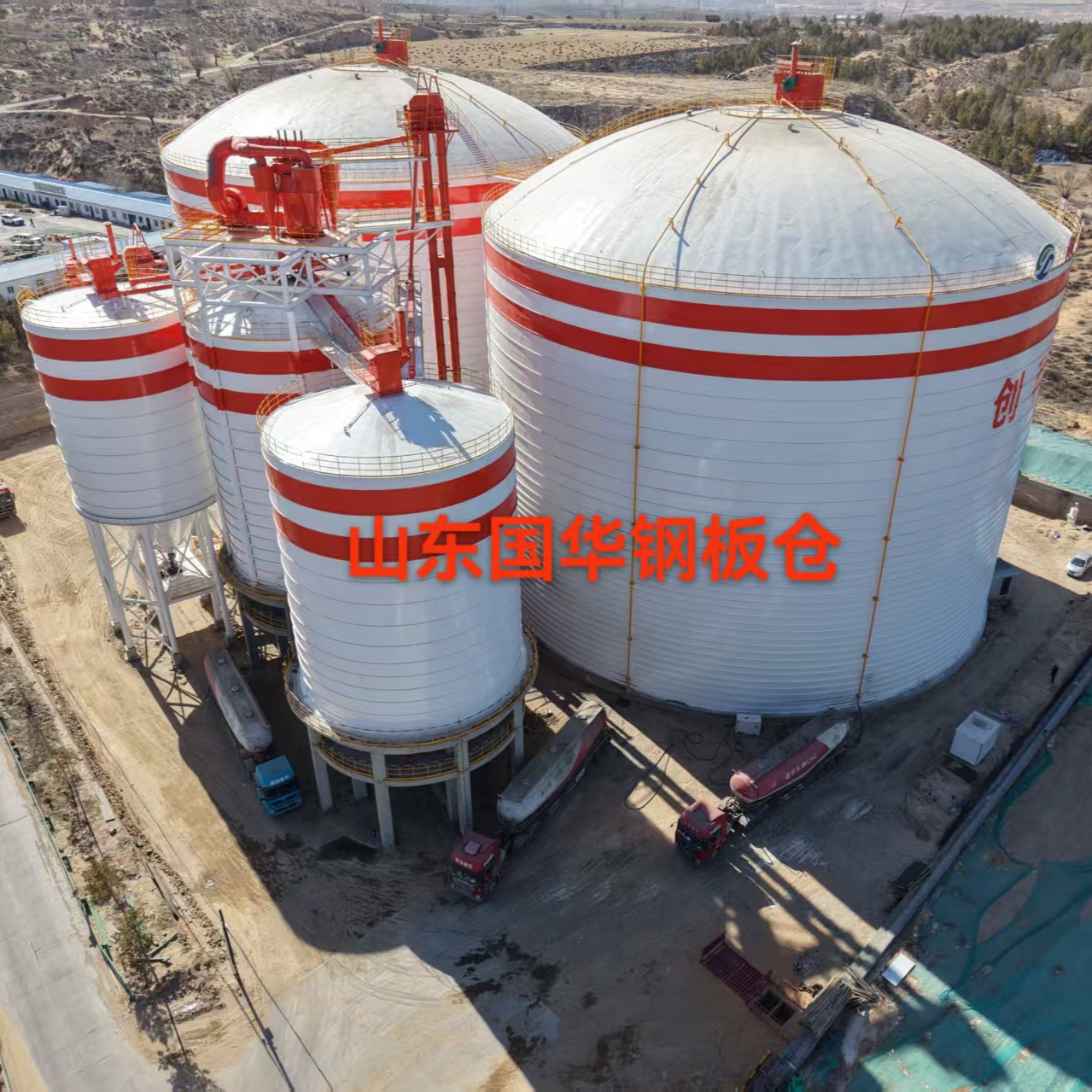
Ring arrangement: Arranged in a ring along the inner wall of the storage bottom, suitable for small steel plate silos (diameter ≤ 10m).
Grid Layout: Forms a grid pattern on the bottom plane of the warehouse, with spacing of 0.5-1.0m, suitable for large steel plate silos (diameter > 10m).
Conical arrangement: Matches the conical structure at the bottom of the storage, ensuring material flows towards the central discharge opening.
III. Application Scenarios and Effects
Fly ash storage
Question: Fly ash with a high moisture content (8%-12%) tends to cake easily, and traditional vibration breaking is ineffective.
Fluidization Rod Effect: Through 0.3 MPa compressed air fluidization, caking rate reduced to below 3% from 15%, discharge speed increased to 15t/h (originally 8t/h).
Cement Storage
Question: Cement tends to compact if stored in the silo for more than 72 hours; manual cleaning is required during unloading.
Fluidizing Rod Effect: Continuous fluidization keeps cement in a loose state, increasing the discharge rate from 85% to 98%, and shortening the discharge time by 40%.
Mineral Powder Storage
Question: The mineral powder has a fine particle size (D50 < 20μm) and is prone to adhere to the storage wall, leading to residue.
Fluidizing Rod Effect: The fluidizing action separates the mineral powder from the bin wall, reducing the residue from 5t/bin to below 0.5t/bin.
IV. Selection and Installation Points
Selection Criteria
Material Characteristics: Select the permeable layer pore size based on particle size, density, and moisture content (e.g., fly ash at 0.05mm, cement at 0.1mm).
Vessel Dimensions: Calculate the required number of fluidizing rods (N = Bottom Area of Vessel / Coverage Area per Rod) to ensure uniform fluidization.
Compressed Air Parameters: Pressure 0.2-0.5 MPa, flow rate determined by the storage volume (e.g., for a 1000 m³ storage, it requires 15-20 m³/min).
Installation Requirements
Levelness: The flatness error of the fluidizing rod installation surface is ≤ ±5mm to prevent air leakage.
Spacing Control: Adjacent fluidizing rod spacing error ≤ ±100mm, ensuring overlap in the fluidization area.
Sealing Treatment: The connection between the fluidizing rod and the bottom of the silo is sealed with silicone to prevent material leakage.
V. Maintenance and Troubleshooting
Routine maintenance
Clean breathable layer: Use compressed air to blow clean the breathable layer every 3 months to prevent material blockage.
Check for air tightness: Conduct a pressure test annually (0.6 MPa holding pressure for 30 minutes, pressure drop ≤ 0.05 MPa).
Common Faults and Solutions
Poor fluidization effect: Check if the compressed air pressure meets the standard and if the permeable layer is blocked.
Pipe deformation: Replace damaged fluidizing rods, adjust installation spacing.
Leak at the joint: Retighten the connector or replace the seal.