


One,Product Overview:
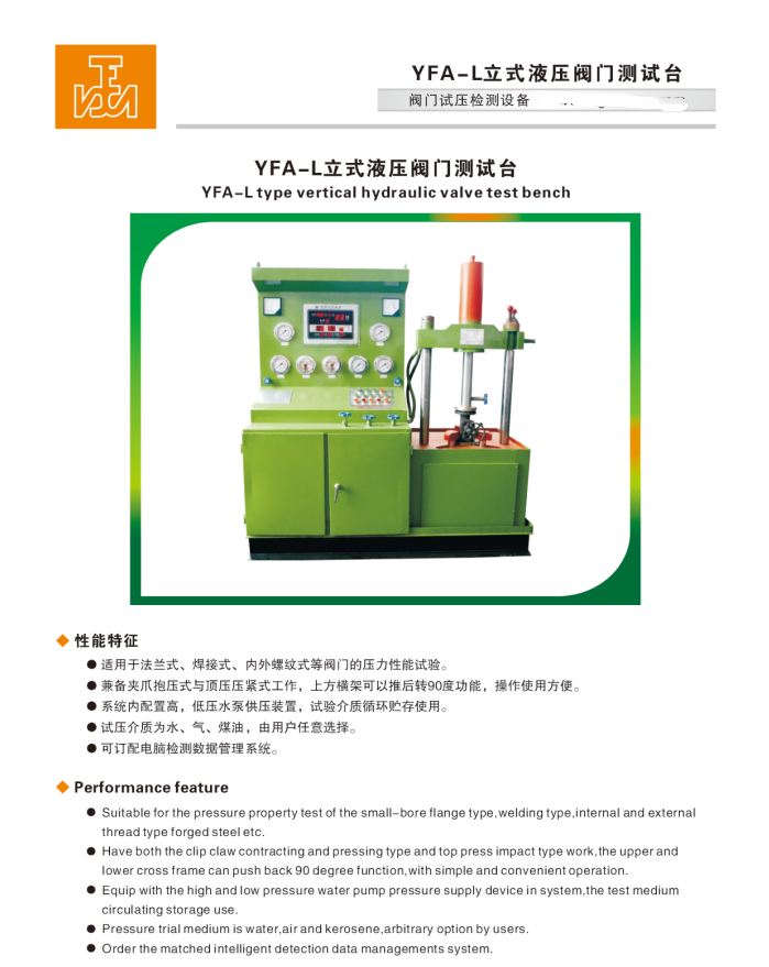
YFA-L Type hydraulic valve test bench, which is based on our company's years of experience in producing valve testing equipment, is strictly manufactured in accordance with GB/T13927-2008 "General Valve Pressure Test" and JB/T26480-2011 "Testing and Inspection of Valves".American Petroleum Institute StandardsDesign and production require test pressure specifications according to API 598 and other standards.
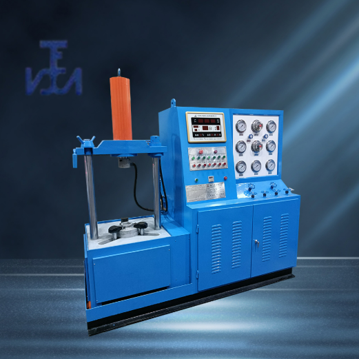
This unit integrates hydraulic, mechanical, electrical systems, pressure-supplying devices, and a medium storage circulating water tank into one. The entire testing process is automatically controlled and executed by hydraulic and electrical components. It boasts advantages such as a reasonable structure, comprehensive functions, stable performance, ease of operation, and high level of automation. It is widely used in high, medium, and low-pressure direct flanged valve testing for pressure-sealing performance and shell strength endurance. Suitable valve types include gate valves, stop valves, check valves, ball valves, and butterfly valves, making it suitable for valve manufacturers, the petrochemical industry, and hydropower stations.Natural GasIdeal valve testing and inspection equipment for industries such as pipe fitting manufacturers, wastewater treatment plants, valve maintenance stations, and more.
II. Specification Range:
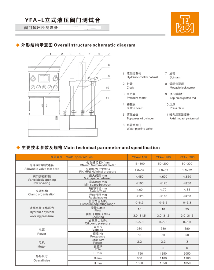
DN15-300mm
Three, Pressure Range: 1.6-42.0 (MPa) / 150-2500 (Class)
IV. Performance Features:
1. The equipment features a structure with a workbench installed below. A set of three-jaw hydraulic clamping mechanism is evenly mounted on the workbench. An adjustable hydraulic thrust cylinder is also mounted on the workbench. The thrust cylinder can rotate backward 90 degrees for valve mounting and sealing test observation, making it convenient for handling and sealing tests. It is suitable for various types of valves such as flanged, welded, socket-weld, gate valves, stop valves, check valves, ball valves, and butterfly valves. The tested valve is not affected by any external force during clamping.
2. The sealing method uses a valve face seal. During the valve sealing test, the hydraulic clamp grips the back of the flange. For strength tests, the bevel face or flange plane is used for sealing, and it is securely clamped by the top pressure cylinder. The clamping force isContinuous pressure regulation or stepless pressure increase via button to the desired pressure value.
3. The test bench features a dual-system for air and water, with bidirectional pressure intake and release, equipped with a leak test port. The system is pre-configured with high and low-pressure pumps, allowing direct hydrostatic testing. The high and low-pressure pumps are equipped with automatic control functions. The gas source is user-provided. The liquid testing medium can be recycled and stored for use, offering energy-saving, environmental-friendly, low-cost investment, and high work efficiency.
4. The equipment is equipped with reliable safety protection measures, featuring an interlocked联动 function in the locking mechanism. When pressure is present within the valve cavity, the locking cylinder will hold and relax only after the pressure is completely exhausted, preventing accidental operation hazards and ensuring safe usage.
V. Usage Instructions:
1. Fill the hydraulic system oil tank with 30#-46# hydraulic oil or 20# mechanical oil, ensuring the oil level does not fall below the oil gauge's lower limit.
2. Power on, press the oil pump start button, check if the motor is rotating in the correct direction (clockwise).
3. Adjust the hydraulic system pressure to 5.0 MPa for normal operation.
4. Sealing test fixture method: Retract the point motion clamp to a position larger than the outer diameter of the valve flange being tested. Select a sealing disc compatible with valve testing and install it on the workbench. Place the valve on the sealing plate. Retract the point motion clamp to a height above the valve flange thickness, advance the clamp, move it close to the valve flange, and then clamp and grip the back of the valve flange. Strength test fixture method: The opposite end face seal is held in place by a thrust cylinder, based on the valve orifice size and pressureRefer to the (pressure required for cylinder clamping chart) to adjust the clamping pressure. For pressures exceeding the pump source by more than 5.0 Mpa, press the (clamp booster) button to increase the pressure to the desired level.The boost button can be pressed multiple times, with each interval being approximately 3-5 seconds, and the maximum pressure reaching 30MPa.
Section 6: Gas Pressure Test:
1. Seal Pressure Test: Assemble the sealing test fixture according to the method, and all assembly is complete (1).Close: Total inlet valve → Upper inlet valve → Lower pressure relief valve → Test butterfly valve. (2) Open: Lower pressure gauge switch → Lower inlet valve → Inject gas into total air inlet valve. Close (total air inlet valve) when the air pressure reaches the required pressure value. (3) Enter the pressure holding timing phase. When the pressure holding time is up, check for bubble leakage on the sealing surface and pressure drop on the gauge to determine if the valve's sealing performance is合格.
2. Gaseous Strength Pressure Test: Based on the sealed test fixtureSealed by a top-tight cylinder pressing against the opposite end face, based on the valve port diameter and pressureAdjust the clamping pressure according to the (Pressure Chart for Cylinder Clamping Requirements).(1)Shut off: Total inlet valve → Left and right pressure relief valves → Leak detection switch. (2) Open: Test valve → Upper and lower pressure gauge switches → Inject gas into the total inlet valve. Close (total inlet valve) when the pressure reaches the required value, and spray foam agent on the valve body surface. (3) Enter the pressure holding timing phase. When the pressure holding time is up, check for bubble leakage at the valve connection seal surfaces and the valve body surface, and if the pressure gauge has dropped pressure, to determine if the valve's strength performance is qualified. (4) After testing, open the pressure relief valve, exhaust the pressure, and remove the valve.
Section 7: Water Pressure Test
Water-tightness and pressure test
Similarly, pressure-sealed test fixture (1),Set the low-pressure pump electrical contact pressure to 1.8 (Mpa). Adjust the electrical contact pressure gauge (with a sealed pressure of 2.5MPa as an example) by moving the red pointer to 2.5MPa. (2) Close: Total inlet valve → upper water inlet valve → lower pressure relief valve → lower pressure gauge switch → valve under test. (3) Open: Total water inlet valve → lower water inlet valve. (4) Start the low-pressure pump to fill with water. When the low-pressure pump pressure reaches the set value of 1.8 (MPa), it indicates that the right valve chamber is full of water, and the low-pressure pump will automatically stop. The high-pressure pump will then automatically start to supply pressure. When the high-pressure water reaches the set value of 4.0 (MPa), the high-pressure pump will automatically stop, and the pressure maintenance timing (such as 2 minutes/client-defined) will begin. Check for any leaks on the valve sealing surface and the housing surface, and ensure the pressure gauge is stable, to determine if the valve's strength and pressure are up to standard.
2、Water Strength Pressure Test:
Similarly, the pressure testing valve mounting is complete, (1)Set the low-pressure pump electrical contact pressure to 1.8 (Mpa). Set the electrical contact pressure gauge (use 4.0 Mpa as an example for strength pressure; adjust the red pointer of the gauge to 4.0 Mpa). (2) Close: Total inlet valve → Upper and lower pressure relief valves → Upper and lower pressure gauge switches. (3) Open: Total inlet water valve → Test valve. (4) Start the low-pressure pump to fill water; upon reaching the set pressure of 1.8 (MPa), it indicates the valve cavity is filled with water, and the low-pressure pump will automatically stop. The high-pressure pump will then automatically start to supply pressure; when the high-pressure water reaches 4.0 (MPa), the high-pressure pump will stop automatically, entering the pressure holding time (e.g., 2 minutes/client-defined). Check for any leaks at the valve connection seal and on the valve body surface, and ensure the pressure gauge is stable, to determine if the valve's strength pressure test is passed. (5) After testing, release all pressure, release the button, and remove the valve.
Section 8: Usage Precautions and Requirements:
1. Ideally, arrange the site in a level indoor space, set the horizontal position, and secure the footer with concrete. The operating environment temperature should be between (1-40)°C, either at room temperature or in a heated workshop during winter. Surroundings should be free from high concentrations of dust and corrosive gases, and avoid proximity to areas with grinding wheels or polishing machines due to poor conditions. Ensure good ventilation; leave at least a 1m space around the equipment for ease of operation and maintenance.
2. Operators must undergo professional training before starting work, adhere to standard procedures, and strictly avoid exceeding specifications or pressure. Non-professionals are prohibited from operating.
3. Operators are strictly prohibited from leaving their posts during the pressure testing process. They must continuously monitor the pressure to prevent it from exceeding safe limits.
4. After the test is completed, the pressure must be released to zero before the clamping jaws can be released. The power should be disconnected during non-use periods.
5. Regularly add lubricant to all moving parts of the testing bench to maintain cleanliness and smooth operation.
6. Use 46-grade anti-wear hydraulic oil (use antifreeze 46-grade anti-wear hydraulic oil below 0℃), ensuring the oil level does not fall below the indicator's lower limit. Regularly check the oil level and hydraulic oil; after one year of use, it should be cleaned.Washing OilBox, replace with new oil.
7. Water source must be clean and free of impurities. Water quality deterioration should prompt timely replacement. Refill with rust-proof powder as needed to meet testing requirements. To ensure the test valves are not corroded, it is usually necessary to add rust-proof powder regularly in the circulating water tank to prevent rusting that may affect the normal operation of pipes, pumps, and check valves due to medium water.
Note: Common rust prevention powders include:Sodium nitriteSodium sulfonate, sodium potassium sulfonate (non-toxic powder).
8. The work surface of the equipment should be kept clean, and there should be no debris between the test valve flange and the test pressure blank flange.