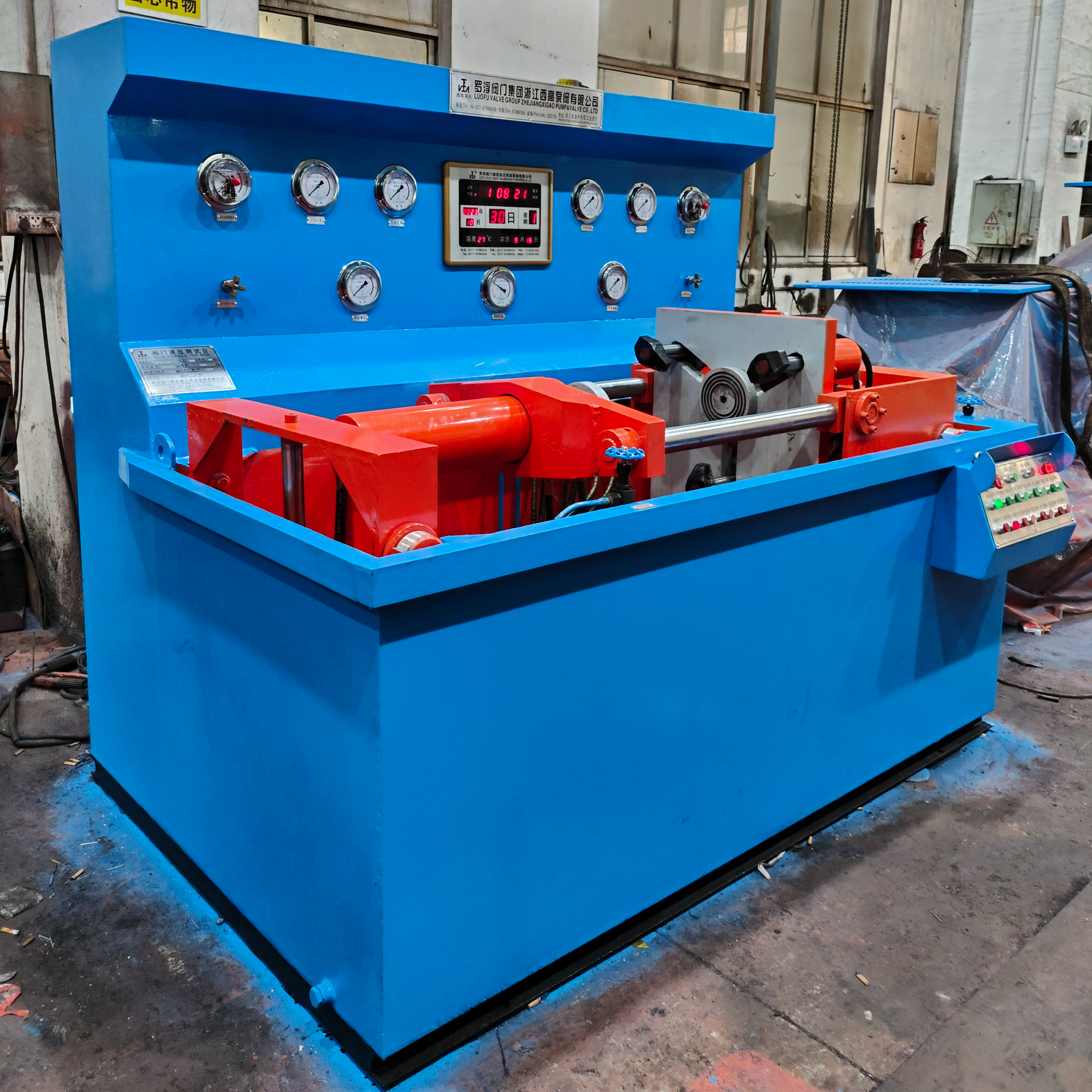


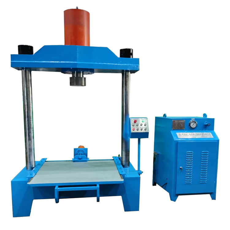
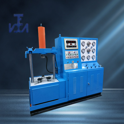
I. Product Overview:
YFA-FQ Type hydraulic valve test bench, which is developed based on our years of experience in manufacturing valve testing equipment, strictly in accordance with GB/T13927-2008 "General Valve Pressure Test" and JB/T26480-2011 "Valve Testing and Inspection."American Petroleum Institute StandardDesign and production requirements for API 598 and other specifications' test pressure.
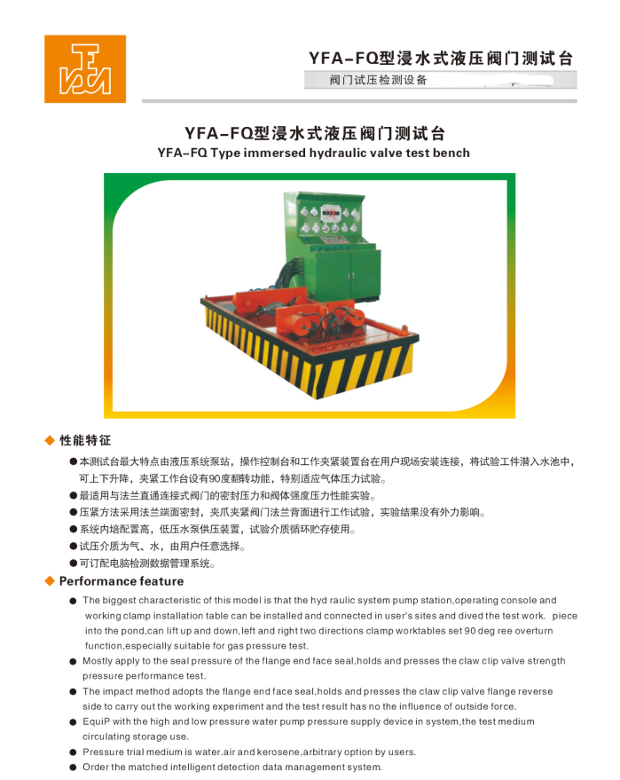
This unit integrates a hydraulic system, mechanical system, electrical system, pressure supply device, and a medium storage circulating water tank. The entire testing process is automatically controlled and executed by hydraulic and electrical components. It boasts advantages such as reasonable structure, comprehensive functions, stable performance, easy operation, and high level of automation. It is widely used in high, medium, and low-pressure direct flanged valve tests for pressure-sealing performance and shell strength. Suitable valve types include gate valves, stop valves, check valves, ball valves, and more. It is suitable for valve manufacturers, the petrochemical industry, and hydropower stations.Natural GasIdeal valve testing and inspection equipment for industries such as pipeline fittings, wastewater treatment plants, valve maintenance stations, etc.
Section II: Specification Range:
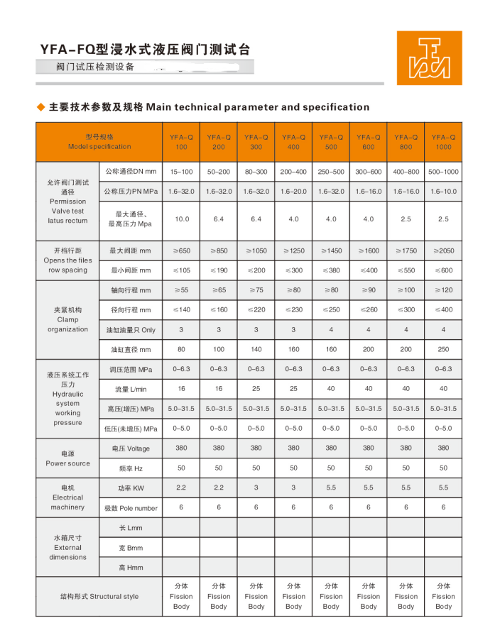
DN15-800mm
Three, Pressure Range: 1.6-63.0 (MPa) / 150-2500 (Class)
IV. Performance Features:
Valves such as gate valves, stop valves, check valves, ball valves, etc., suitable for direct flange connections, use flange face sealing for tightening, with a hydraulic clamp gripping the back of the flange, adjustable clamping force. Test results were unaffected by additional external force. During the valve testing, the right-hand operating disk features a 90-degree flip function, particularly suitable for gas tightness performance testing. The other operating disk can be moved forward and backward, with the length of the opening spacing freely adjustable. Valve length is unrestricted, greatly improving work efficiency.
Clamping Method: Each bidirectional working plate is equipped with a removable hydraulic clamping mechanism. It can automatically synchronize and adjust the position of the clamping jaws according to various valve specifications, achieving automatic centering and positioning. The hydraulic clamping jaws automatically grip the back of the valve flange, with adjustable clamping force, exerting no external force on the valve itself. The entire clamping process is controlled by an integrated button and executed by hydraulic components.
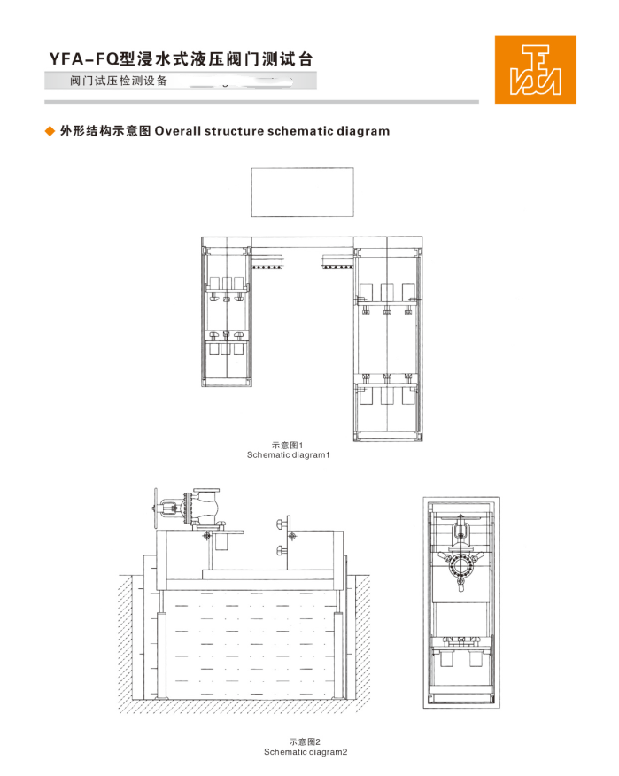
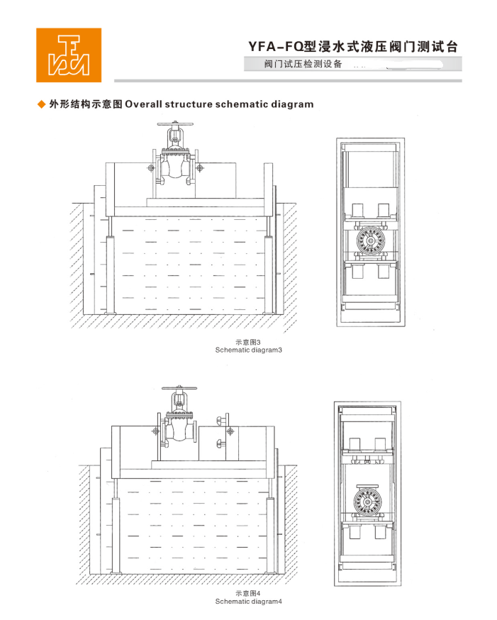
The test bench features up and down lifting capabilities, allowing both the machine and the valve under test to be submerged in water simultaneously. It is particularly suitable for strength, sealing, and gas pressure performance tests of valves, changing the traditional testing method of brushing the valve housing surface with a foaming agent. This innovation shortens testing time and significantly enhances work efficiency, making it the most ideal choice for a dual-air-water testing device.
Hydraulic Valve Test Bench Working Principle and Operation Method:
I. Working Principle:
Select a sealing blank that matches the valve model and install it on the equipment. Push the electrical switch, the equipment power indicator light illuminates, press the oil pump start button, and allow the hydraulic system motor to run. Ensure the motor runs in the correct direction (clockwise), then retract the left moving bracket to a length greater than the valve being tested. Radially move the left and right clamps to exceed the outer diameter of the valve flange, and extend the left and right clamps axially to exceed the thickness of the valve flange.
Secure the tested valve flange against the right-hand workbench with a blind flange, aligning it to the center position. Move the radial clamp, position it close to the valve flange, press the clamp tightening button to reduce the clamp gap, and press against the back of the valve flange to ensure it does not come loose.
Slide the left-hand shelf to the right, close to the valve flange at the other end, align it with the left test blind flange, and position it centrally. Move the left radial clamp towards the valve flange, press the clamp button to shorten the clamp stroke, and securely press against the back of the valve flange, completing the overall clamping of the valve.
During gas pressure testing, the machine and the valve under test can be submerged together in water. For hydrostatic testing, simply raise the machine to the proper position.
Section II: Sealing Pressure Test Method:
Fill the hydraulic system oil tank with 30#-46# hydraulic oil or 20# mechanical oil; the oil level must not be below the lower limit of the oil gauge.
2. Power on the unit, press the oil pump start button, and check if the motor rotates in the correct direction (clockwise).
Adjust the hydraulic system pressure to 5.0 MPa for normal operation.
4、Secure the tested valve flange to the right workbench with a blind flange, aligning it to the center position. Move the radial chuck closer to the valve flange, press the clamping button to shorten the chuck gap, and press against the back of the valve flange to ensure it won't come loose.
5. Close: Left water inlet valve → Main air inlet valve → Right pressure relief valve → Test valve → Right pressure gauge switch.
6. Open: Right water valve → Main water valve.
7. Refer to the (Pressure Comparison Chart for Cylinder Clamping) to adjust the clamping pressure. For pressures exceeding the pump source by 5.0 Mpa or more, press the (Right Claw Pressure Increase) button to increase the pressure to the required clamping level. Press the (Top-Right Flip) button to flip the working plate to a horizontal position.
8. All assembly is complete. Set the low-pressure pump electrical contact pressure to 1.8 (Mpa). Set the electrical contact pressure (take the valve sealed at 4.0MPa as an example, adjust the red pointer of the electrical contact pressure gauge to 4.0MPa).
9. Start the low-pressure water pump. Once the low-pressure water pressure reaches the set value of 1.8 (MPa), it indicates that the valve chamber is filled with water. The low-pressure pump will then automatically stop, and the high-pressure pump will automatically start to supply pressure. When the high-pressure water reaches the set value of 4.0 (MPa), the high-pressure pump will automatically stop, and enter the pressure holding timing period (such as 2 minutes/client-defined). Check the sealing surface and connection points of the valve, as well as for any leaks on the valve body surface and for any downward deflection on the pressure gauge, to confirm the sealing surface performance is up to standard. After the test is complete, open the (pressure relief valve) switch to exhaust the pressure and proceed to the next test.
Note: The process and testing methods for left-side mounting are similar to those for right-side.
Section 3: Tensile Strength Testing Method:
1. Intensity pressure test: On the basis of the sealed test fixture process, advance the left movable frame towards the right-hand worktable, approaching the opposite end valve flange. Press against the left test blind plate and align with the center position. Move the left radial clamp, approach the valve flange, press the clamp button to shorten the clamp stroke, and securely press against the back of the valve flange. The overall fixture of the valve is completed.
2. Refer to (the pressure required for cylinder clamping comparison table) and increase the pressure to the required value. Once everything is clamped, set the low-pressure water pump electrical contact pressure to 1.8 (Mpa). For the electrical contact pressure (take the valve with a strength pressure of 6.0 MPa as an example), adjust the red pointer on the electrical contact pressure gauge to 6.0 MPa.
3. Open: Right inlet valve → Left inlet valve → valve under test.
4. Shutdown: Total intake valve → Right pressure relief valve → Left pressure relief valve → Right pressure gauge switch → Left pressure gauge switch.
5. Start the low-pressure water pump. When the low-pressure water pressure reaches the set value of 1.8 (MPa), it indicates that the valve chamber is fully filled with water. The low-pressure pump will automatically stop, and the high-pressure pump will automatically start to supply pressure. When the high-pressure water reaches the set value of 6.0 (MPa), the high-pressure pump will automatically stop, and enter the pressure holding timing period (such as 2 minutes/client-defined). Check the valve connection areas, as well as for any leaks on the valve body surface and if the pressure gauge is functioning properly, to confirm if the valve strength pressure test is合格. After the test, open the (pressure relief valve) switch, exhaust the pressure, release the clamps, and remove the valve.
Section 6: Usage Precautions and Requirements:
1. Ideally, the site should be arranged in a level indoor space, properly leveled, with concrete footings in place. The environmental temperature should be between 1-40℃ for normal conditions or in a heated workshop during winter. The area should be free from high concentrations of dust and corrosive gases, and should not be near grinding wheel or polishing machines in poor conditions. Good ventilation is required, and at least a 1m space channel should be left around the equipment installation for ease of operation and maintenance.
2. Operators must undergo professional training before assuming their positions, adhere to standardized procedures, and are strictly prohibited from using equipment beyond its specifications or pressure limits. Non-professionals are advised not to operate.
3. Operators are strictly prohibited from leaving their posts during the pressure testing process. They must continuously monitor the pressure to prevent it from exceeding safe limits.
4. After completion of the test, the pressure must be relieved to zero before releasing the clamp. The power supply should be disconnected during non-operational periods.
5. Regularly add lubricant to all moving parts of the test bench to maintain cleanliness and smooth operation.
6. Use 46-grade anti-wear hydraulic oil (for temperatures below 0℃, use antifreeze 46-grade anti-wear hydraulic oil). The oil level must not be below the indicator's lower limit. Regularly check the oil level and hydraulic oil; after one year of use, it should be cleaned.Wash OilCase, replace with new oil.
7. Water source must be clean and free of impurities. Water quality deterioration requires immediate replacement, and new rust-proofing powder should be added. It must meet testing requirements. To ensure that testing valves are not corroded, it is typically necessary to add rust-proofing powder regularly to the circulating water tank to prevent the medium water from causing rust on pipes, pumps, and check valves, which could affect normal operation.
Note: Common rust preventive powders include:Sodium nitriteSodium sulfonate, sodium benzenesulfonate (non-toxic, powdered form).
8. The equipment work surface should be kept clean, and there should be no debris between the test valve flange and the test pressure blank flange.