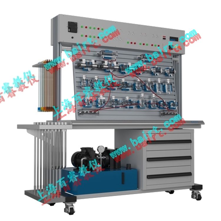


TY-B Type Double-Sided Transparent Hydraulic Test Bench

I. Product Introduction
To quickly adapt to the development across various fields and cultivate a large number of skilled workers, technicians, engineers, and operators with a solid understanding of hydraulic transmission fundamentals and practical skills, and to deploy them across various fronts of socialist construction, our company, based on the requirements of textbooks such as "Hydraulic Transmission," "Principles of Hydraulics," and "Basic Mechanics," and considering the characteristics of domestic hydraulic components, has referred to advanced foreign technologies and undergone years of efforts and exploration. We have developed a transparent hydraulic transmission experimental platform by relying on theory and using experimentation as a means, adopting high-precision machining processes to overcome a series of practical difficulties such as the thermoplastic nature, ease of deformation, poor mechanical strength, and high surface finish and structural precision requirements of transparent organic plastics. To enhance space utilization, we have specifically designed double-sided experimental platforms, which have reduced costs and increased efficiency.
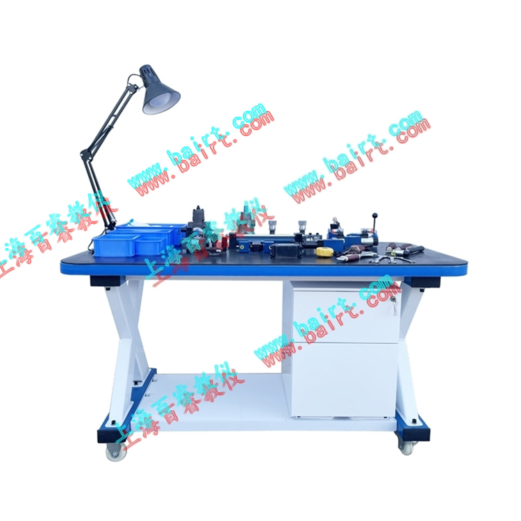
Mechanical requirements for hydraulic transmission vary widely, typically comprising basic functional circuits such as directional control, pressure control, speed control, and sequence control loops. The main frame of this experimental bench is meticulously crafted from 1.0mm cold-rolled steel plate, finished with baked paint for aesthetics and durability. It is equipped with four high-quality, axially mounted swivel casters for easy mobility. The cabinet is divided into two sections below; the left side is for the hydraulic pump station, and the right side is a storage cabinet used to house transparent hydraulic components.
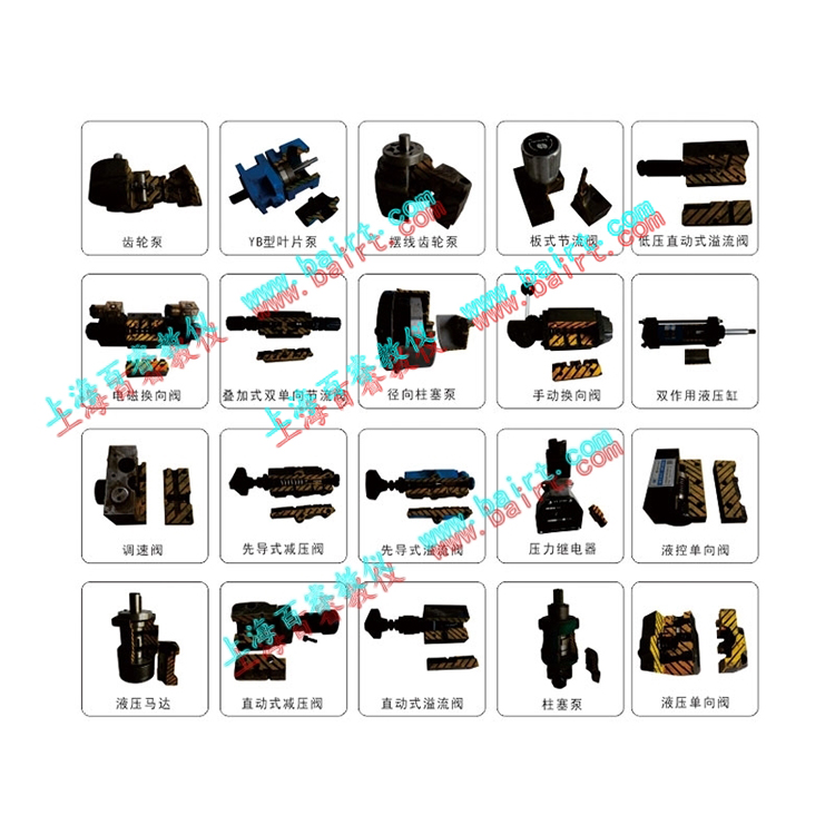
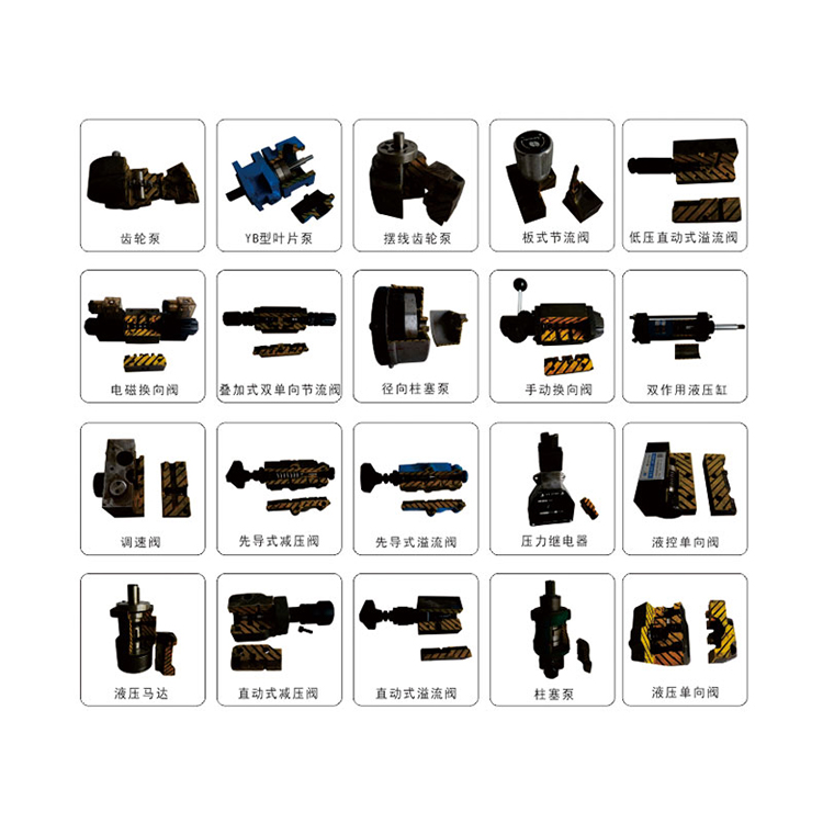
Each hydraulic component features a sky blue elastic card-type transition base, offering an aesthetically pleasing and generous overall appearance, sturdy and durable structure, and easy operation. This demonstration system, through experimental demonstrations of the 18 basic control circuits of the four major fundamental functions (with expanded experiments up to 60), enables students to familiarize themselves with the structures, properties, and applications of over 20 common hydraulic components. It also helps them master the working processes and principles of over a dozen basic circuits, enhancing their ability to troubleshoot and solve problems. The experimental demonstrations inspire and spark interest, allowing for the expansion of experiments on other oil circuits within the tolerances of the various components provided by this product (such as oil circuit design, graduation projects).
This hydraulic test bench product references the characteristics of domestic hydraulic components, making it more suitable for domestic teaching requirements. The system utilizes transparent hydraulic components, a combination slot structure, movable pipeline joints, and universal electrical wiring. With the included tools and materials, and following the experimental guidebook, it allows for convenient control experiments of various common hydraulic transmissions. It enables students to understand the principles, structures, and working processes of the oil paths and internal hydraulic components, making it an ideal equipment for hydraulic transmission teaching.
II. Main Technical Specifications
Power Supply:
220V 50Hz (Mains) Two-phase ~ 220V ±10%
Rated Power: ≤1KW Rated Pressure: 0 ~ 1.0 Mpa
2. Laboratory Bench
Dimensions: 1500mm (Length) × 750mm (Width) × 1800mm (Height).
The package weight is approximately 250 kg.
The training workbench is composed of an iron double-sided main body, an electrical cabinet, and an aluminum alloy panel (T-slot). Made from 2mm thick Baosteel high-quality cold-rolled steel plate and spray-painted material, it is both aesthetically pleasing and sturdy. Equipped with four high-quality axis-type swivel casters at the bottom, it is easy to move. The cabinet is divided into two parts below: one side for placing pump stations, and the other as a storage cabinet for hydraulic components.
3. PLC Programmable Logic Controller
Programmable Logic Controller (PLC): Standard with German Siemens S7-200 SMART series, CPU SR20, 20 I/O points, relay output type.
Electrical control uses a DC 24V power supply, solenoid valve output control port, proximity switch, wiring cables, power outlets, buttons, indicator lights, etc.
Standard configuration brands are recommended by our company. Customers can select optional configurations according to their own needs. Considering the impact of price, we will further communicate and adjust your selections.
4. Hydraulic Test Pump Station
Working Voltage: AC 220V, Motor Power: 750W, Motor Speed: 0-1450 RPM
The pump is a low-pressure gear pump, model CB-B2.5, with a rated displacement of 2.5ml/rev.
Fuel Tank: Nominal capacity 40L; equipped with liquid level and oil temperature gauges, oil suction and filter, air filter, etc.
5. Demonstration Experiment
Flow rate requirements for the oil circuit only need a pressure of 0.3-0.5 Mpa (Oil pump maximum pressure: Pmax = 1.2 Mpa)
III. Key Features:
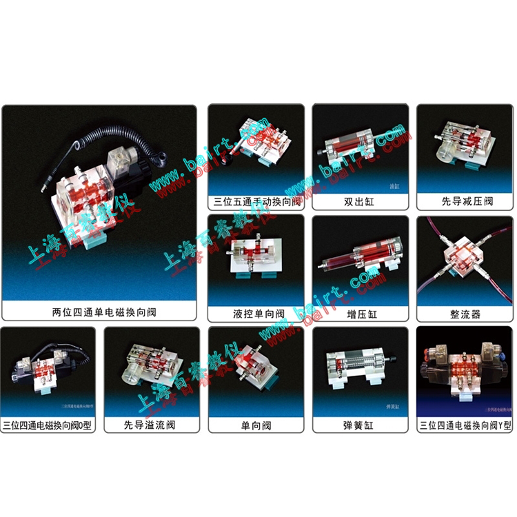
The valve body is made of transparent acrylic material, allowing for a clear observation of the internal structure and operation process of the hydraulic transmission unit.
2. Leak-proof quick connect interfaces simplify, speed up, and ensure cleanliness in the assembly of experimental circuits. Each hydraulic component comes with an installation base, allowing for easy and flexible placement on the aluminum alloy profile panel. Oil path connections use open/close type self-locking quick-change joints, making disassembly and connection convenient without oil leakage.
3. Independent component modules with convenient installation (aluminum alloy profiles with T-slot form for the operating panel) allow for the flexible combination of various experimental modules to construct diverse experimental circuits.
4. The maximum allowable pressure for hydraulic components is 1.2 Mpa, with a rated working pressure of 0.8 Mpa, making it a safe low-pressure testing system.
5. Controlled by a programmable logic controller (PLC), optimizing the control program
6. Enhanced configuration simulation software for added functionality.
7. Enhanced with hydraulic simulation software, featuring virtual circuit connection and fault detection capabilities.
Four: Lab Bench Function:
Hydraulic transmission basic circuit experiment
1) Sequential action circuit controlled by proximity switch
2) Differential Circuit
3) Three-way five-port manual directional valve's directional circuit
4) Multi-stage pressure regulating loop
5) Throttle valve oil throttling speed regulating circuit
6) Throttle Valve Return Flow Throttling Speed Control Circuit
7) Two-stage pressure regulating circuit
8) Pressure Relief Valve's Pressure Reducing Circuit
9) Throttle Valve Series Speed Transfer Loop
10) Speed changeover circuit for parallel throttle valves
11) Three-way four-way solenoid valve (M-type) unload circuit
12) Pilot-operated relief valve unload circuit
13) Sequential Action Circuit Controlled by Sequential Valve
14) Pressure relay-controlled sequential operation circuit
15) Sequential valve's balancing circuit
16) Two-speed control loop
2. Programmable Logic Controller (PLC) electrical control experiment, integrated mechanical, electrical, and hydraulic control experiment format.
1) Learning PLC instruction programming and ladder diagram programming
2) Learning and Usage of PLC Programming Software
3) Communication between PLC and computer, online debugging and monitoring
4) Optimization of PLC control for hydraulic transmission
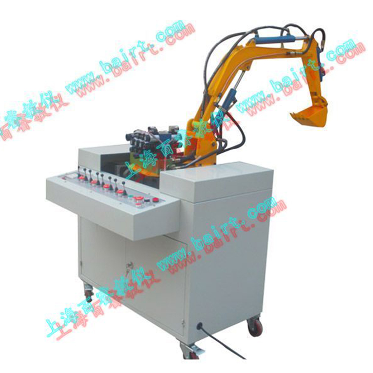
3. Excavator Simulation Kit (Optional accessory)
1) Observation of hydraulic transmission component structures, disassembly and assembly, as well as learning and analysis of the principles of hydraulic control systems.
2) Hydraulic Excavator Demonstration and Control Experiment.
Excavation operation, bucket and dipper arm working in combination for experimental purposes.
② Unloading operation, boom and bucket operation; the large arm can adjust its height position simultaneously.
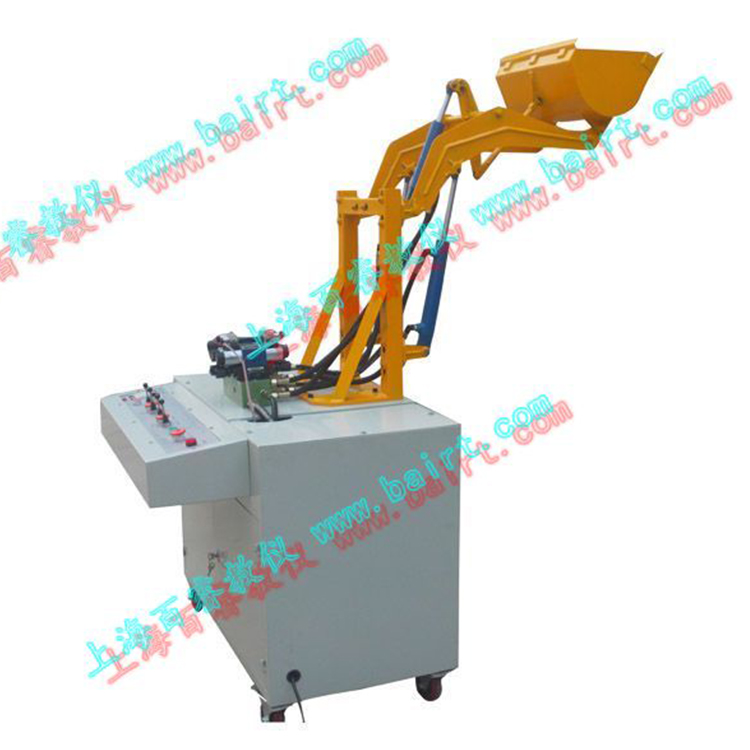
4. Loader Simulation Kit (Optional accessory)
1) Observation of the structural components of hydraulic transmission, disassembly and assembly, as well as the study and analysis of the principles of hydraulic control systems.
2) Demonstration and control experiment of hydraulic loading machinery.
① Material loading operation, after the bucket is loaded, the arm cylinder extends, causing the bucket to reverse and the boom to lift.
② Unloading operation, bucket unloading (retracting the boom to turn the bucket), and lowering the arm.
Additionally, we offer a variety of construction machinery simulation units, including hydraulic loader simulation units, small hydraulic forklift simulation units, and small hydraulic crane simulation units, for customer selection. Welcome to call for inquiries.