


Key Features
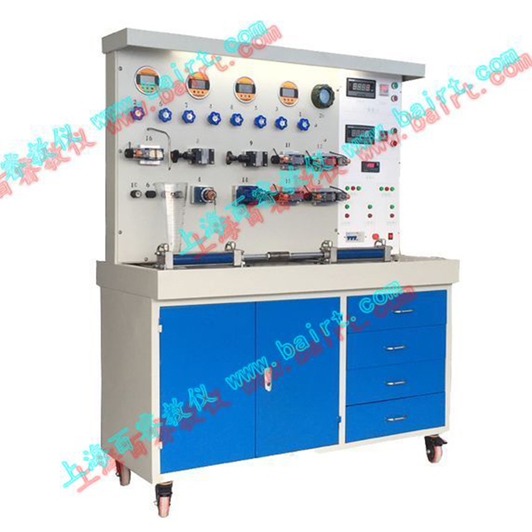
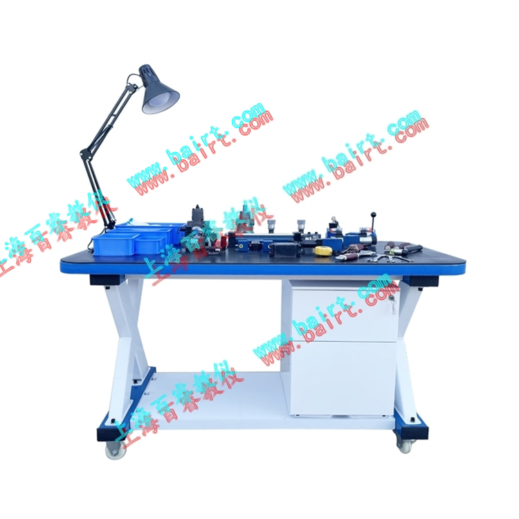
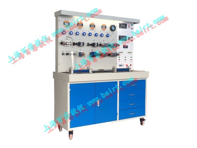
1. The lab table is arranged vertically, with hydraulic valves mounted on the cast iron panel in a vertical setup, accompanied by pressure gauges and flowmeters to display flow and pressure.
2. Equipped with lighting fixtures.
3. Pressure and flow parameters are adjusted on the front, while the pipes are securely connected on the back with steel pipes, ensuring good safety and a tidy pipeline layout.
4. Two opposed loading hydraulic cylinders are securely fastened to the cast iron surface with screws to achieve double-cylinder opposing loading. The experimental pressure can be ≥7MPa. An oil collection device is set on the surface to prevent oil leakage.
5. The hydraulic station is powered by a fixed-displacement pump, located beneath a covered experimental bench. Simultaneously, performance tests of the fixed-displacement pump and loading experiments with variable loads can be conducted.
Technical Specifications
Maximum Pressure: 63 kg/cm2, Oil Pump YB1-6, Displacement: 6ml/r (Total of 2 units)
2. Motor Model: 2HP4P (Total 2 units); Power: 1.5 Kw, Speed: 1450 rpm
3. Fuel Tank: 120L
Dimensions: Length x Width x Height: 1390 x 600 x 1700 (mm)
Experimental Project:
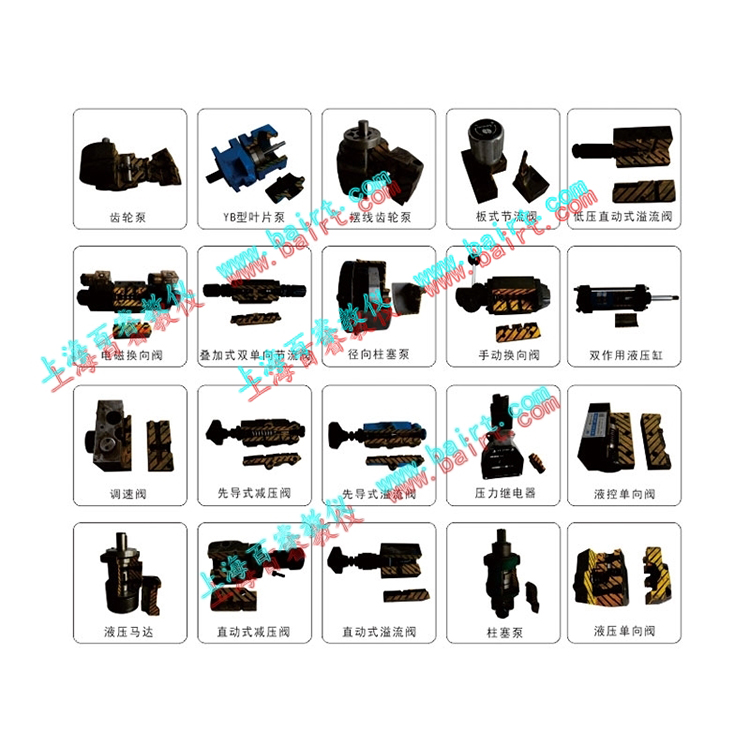
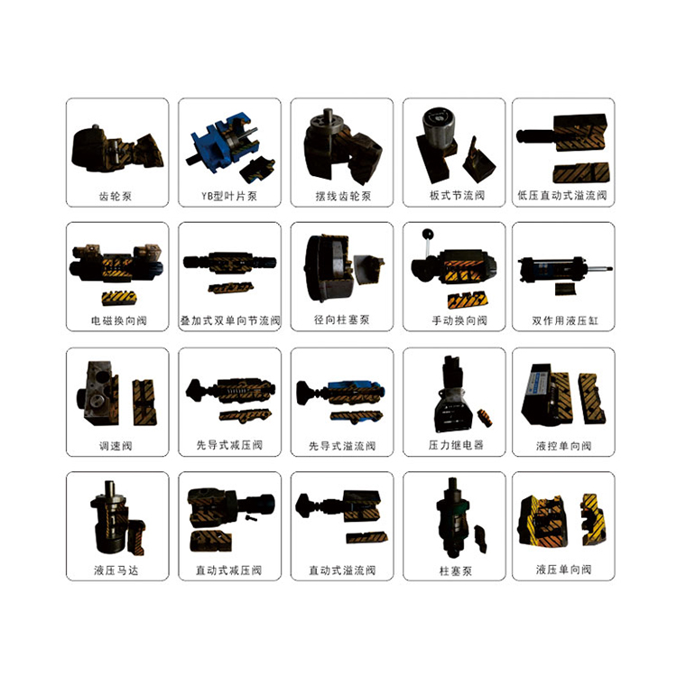
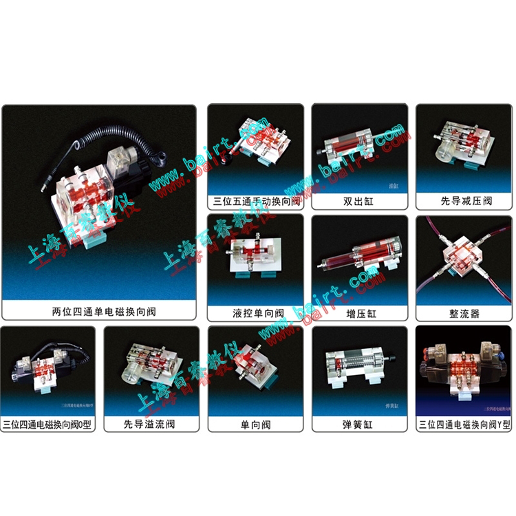
1. Understanding the Operating Principle of Standard Series Hydraulic Components Experiment
2. Hydraulic component performance testing experiment
1) Oil Pump Performance Test (Flow Characteristics, volumetric efficiency, and total efficiency)
2) Static and dynamic experiments of the overflow valve (opening and closing characteristics, pressure overshoot characteristics)
3) Throttle speed control and oil inlet throttle valve speed regulation
4) Throttle valve throttling speed regulation performance test (inlet throttling speed regulation, return throttling speed regulation, working characteristics in bypass system)
5) Hydraulic System Efficiency Test
3. Creative Design Experimentation in Component Systems.