


YD-A Type Hydraulic Transmission Comprehensive Experimental Bench (Upgraded Version with Fault Diagnosis)


The YD-A type quick-connection hydraulic transmission experimental bench is designed based on modern teaching characteristics and the latest hydraulic transmission curriculum requirements. It utilizes advanced Rexroth technology hydraulic components and unique modular design, forming an easily connected system assembly. This bench meets the experimental teaching requirements for hydraulic transmission courses in colleges and universities, secondary specialized schools, and vocational technical schools; it aims to cultivate students' hands-on, design, and comprehensive application skills, and enhances their innovative design capabilities.
I. Key Features:
1. The system is fully equipped with standard industrial hydraulic components, ensuring safety and reliability, and is closely aligned with industrialization.
2. Fast and reliable connection methods, with special sealed interfaces, ensuring easy and quick assembly for experiments, no oil leakage during disassembly, and clean maintenance.
3. Measurement instruments, convenient measurement methods, easy to use, reliable readings.
4. Utilize Programmable Logic Controllers (PLCs) for communication with microcomputers to achieve electrical automation control, online programmable monitoring, and fault detection.
5. Enhanced configuration simulation software for improved functionality.
6. Enhanced with hydraulic simulation software, featuring virtual circuit assembly and fault detection capabilities.
7. Training, diagnostic, and assessment functions of the experimental bench
System Fault Setting, Diagnostics, and Troubleshooting Training Assessment System
This System Fault Analysis and Exclusion Training Evaluation System is based on traditional circuit and component testing, and data analysis, with upgraded and expanded features. In accordance with the requirements of national model vocational colleges, it mainly includes component hardware faults, electrical component faults, and electrical system faults. Component hardware faults and electrical component faults have independent, identifiable hidden fault codes for teachers' convenience in setting up faults; electrical system faults can be set through human-machine dialogue, and corresponding exam software is provided for troubleshooting the electrical system fault, allowing for assessment of students' troubleshooting abilities.
Parameters and Performance
7.1.1. Equipped with a user-friendly human-machine dialogue interface (optional remote control)
7.1.2. Custom Data Analysis Control Card
7.1.3. Exclusive assessment system, a scientifically rigorous and objective teacher rating system
Description and Key Features of All Parts
7.2.1 The system data analysis control card is capable of fault expansion, featuring ample expansion interfaces.
7.2.2 The exam system features system power management, device locking, unlocking devices, P-IO, temporary departure, forced submission, score viewing, score export, score printing, clearing scores, and clearing test papers.
7.2.3 The exam software includes two modes for assessment setup: manual and randomly generated by the software.
7.2.4 The random exam mode can be set by the software to generate questions randomly, thereby ensuring anti-plagiarism for each assessment.
7.2.5 Power failure protection function ensures automatic saving of settings data and exam results.
7.2.6 Within the software's built-in features, it includes: querying candidates' relevant data information: ID, scores, accuracy, unexcluded faults, time, and exam status.
7.2.7 Teachers have their own independent backend password, allowing them to set critical data and confirm exam results.
List of man-made malfunctions that can be achieved:
7.3.1 The oil pump is operating, but there is no pressure in the main circuit.
7.3.2 Main Overflow Valve – No Overflow
7.3.3 No secondary pressure buildup
7.3.4 Lead-type overflow valve connected to the system, system de-loads
7.3.5 The oil cylinder is not functioning properly.
7.3.6 Various solenoid valves fail to operate normally
7.3.7 Manual directional valve stuck
7.3.8 Simulated Pump Fuel Inlet Filter Clog
7.3.9 Common issues include poor sealing of the pump inlet oil tube and air intake.
7.3.10 Pump Reverse
7.3.11 The pressure relief valve outlet cannot be adjusted to the desired pressure.
7.3.12 Single-direction throttle valve cannot regulate flow
Passive student diagnostics and elimination, with teachers conducting exams within a time limit, automatically generating scores.
Electrical system fault diagnosis, troubleshooting, and assessment
7.4.1 Main Circuit Failure:
The oil pump cannot be stopped.
Emergency stop pressed cannot be stopped
The oil pump fails to start.
Oil pump single-stroke start
7.4.2 PLC Line Fault
PLC powers on, PLC lacks power (wiring fault)
PLC power is on, no input (input common wire fault)
PLC power is on, but there is no output (common line fault in output)
PLC pressure input button has no input (button malfunction)
PLC output is active, panel indicator light is not illuminated (indicator light malfunction)
The proximity switch is activated, but there is no input to the PLC (plug-in fault).
PLC output light is on, no output (plugin fault)
7.4.3 Relay Module Failure
Relevo module button bolt is unresponsive.
The relay module can start but cannot stop.
Relay module has no output
The relay module has no external inputs.
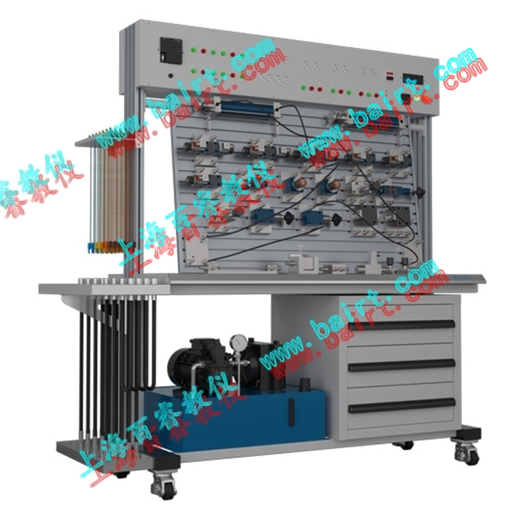
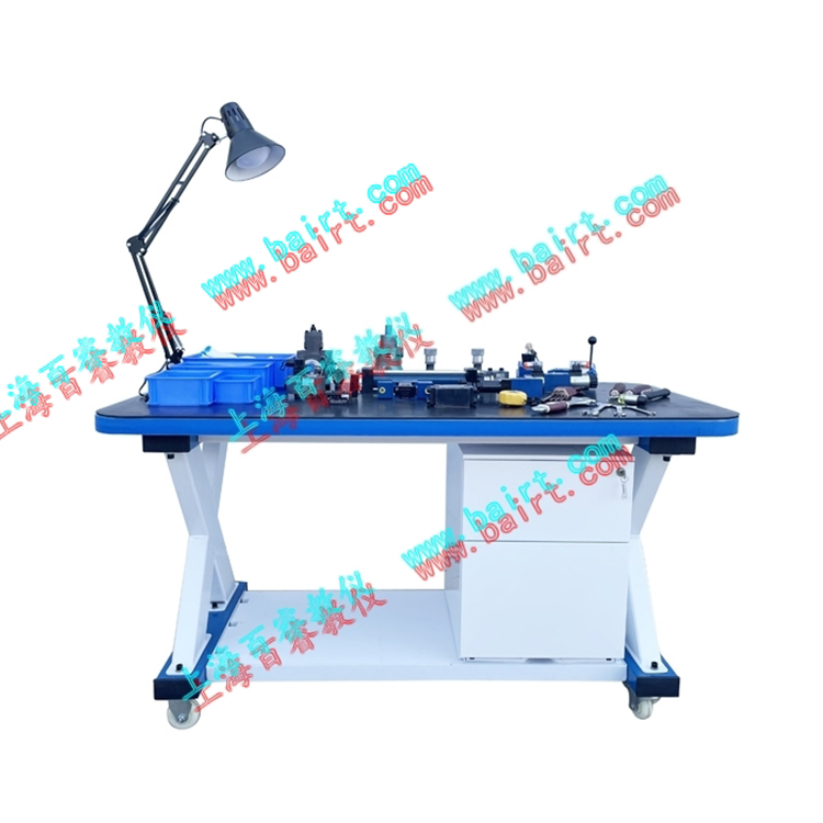
II. Laboratory Bench Composition:
① Laboratory Workbench
Working Power: Three-phase Four-wire 380V, Rated Power: 1.5KW, Rated Pressure: 6.3-7Mpa
The experimental workbench is composed of an iron frame, an electrical cabinet, an oil pipe rack, and an aluminum alloy panel (T-slot). Made from 2mm thick Baosteel high-quality cold-rolled steel plates, it is both aesthetically pleasing and sturdy, featuring four high-quality swivel casters at the bottom for easy movement. The cabinet is divided into two parts below: the left side is for the pump station, and the right side is a storage cabinet for hydraulic components.
Workbench
Main Dimensions: Length x Width x Height = 1500mm x 650mm x 1760mm (Approx. 260kg after packaging)
Optional Desk Attachment: Length x Width x Height = 600mm x 650mm (approx. 20kg for computer attachment)
Optional Fault Setting Diagnostic Training Function
Supplementary Dimensions: 650×650×1500mm
Hydraulic Pump Station
System rated working pressure: 6.3 Mpa (up to 7 Mpa max).
Motor-pump unit (1 unit)
Variable impeller pump - Motor 1 unit
Variable impeller pump: Single-direction, nominal displacement 6.67 mL/r, volumetric efficiency 90%.
Motor: 3-phase AC voltage, power 1.5KW, speed 1450r/min
⑵. Fuel Tank: Nominal Capacity 40L; Equipped with liquid level and oil temperature gauges, oil filter, air filter, plug caps, etc.
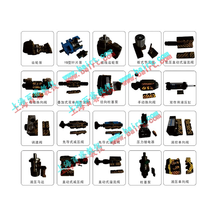
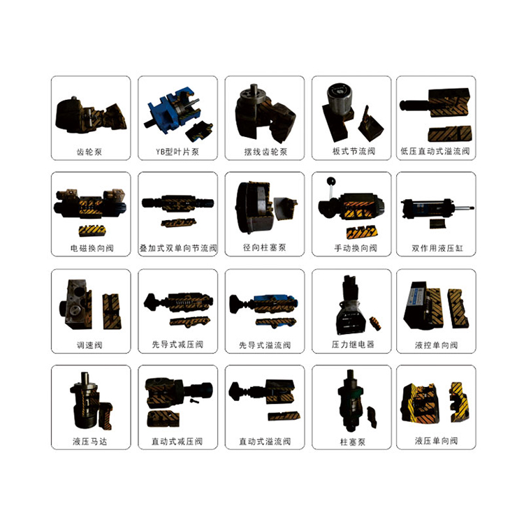
③ Common Hydraulic Components
Hydraulic brands primarily include Beijing Huade Components, known for stable operation and reliable performance. Detailed configurations are listed in the configuration sheet.
Each hydraulic component is equipped with an oilway transition base, allowing for easy and flexible placement on the aluminum alloy panel.
④ Electrical Measurement and Control Unit
Programmable Logic Controller (PLC): Siemens SMART series, CPU SR20, 20 I/O points, relay output format; (Customers can choose PLCs with different brands and configurations to meet their specific needs.)
Power Voltage: AC 220V/50Hz, control voltage is DC 24V, equipped with manual, automatic, and sequential control functions.
Section 3: Hydraulic Training Projects
I. Basic Hydraulic Transmission Circuit Experiment:
Single-stage pressure regulation loop
2. Two-stage pressure regulating loop
3. Pressure Reducing Valve's Pressure Reduction Circuit
4. Sequential Valve's Balance Circuit
5. Directional valve's unload circuit
6. Pilot-operated relief valve unload circuit
7. Pressure-holding self-locking circuit for hydraulic one-way valves
8. Differential circuit
9. Speed control valve short-circuit speed transfer circuit
10. Throttle Valve Feed Throttle Speed Control Loop
11. Throttle Valve Return Flow Throttling Speed Control Loop
12. Throttling valve bypass throttle control circuit
13. Throttle valve oil flow throttling control loop
14. Throttle valve return flow throttling control loop
15. Flow control bypass throttle control loop
16. Throttling valve-controlled unidirectional synchronous loop
17. Two-way four-way electromagnetic directional valve directional circuit
18. Three-way four-way solenoid directional valve directional circuit
19. Two-way four-way manual directional valve directional circuit
20. Sequence Valve-Controlled Sequence Action Circuit
21. Sequence action circuit controlled by proximity switch
22. Sequence action circuit controlled by pressure relay
II) Programmable Logic Controller (PLC) electrical control experiments, integrated mechanical, electrical, and hydraulic control experiments format.
1. Learning PLC instruction programming and ladder diagram programming
2. Learning and usage of PLC programming software
3. PLC communication with computer, online debugging, monitoring
4. Optimization of PLC control for hydraulic transmission
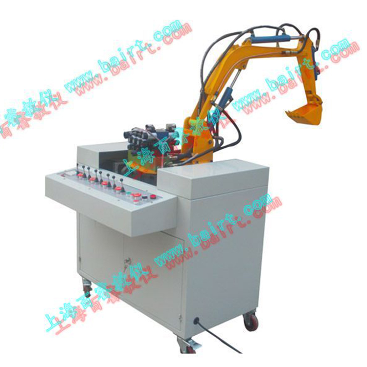
3) Excavator Simulation Kit (Optional accessory)
1) Observation of hydraulic transmission component structures, disassembly and assembly, as well as study and analysis of the principles of hydraulic control systems.
2) Hydraulic Excavator Demonstration and Control Experiment.
Excavation operations, involving combined bucket and dipper arm working tests.
② Material discharge operation, boom and bucket operation, with the ability to adjust the height of the large arm simultaneously.
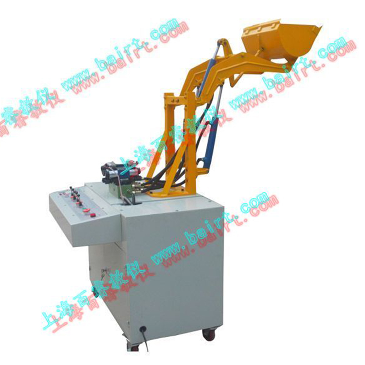
4) Loader Simulation Unit (Optional accessory)
1) Observation of hydraulic transmission component structures, disassembly and assembly, as well as learning and analysis of the principles of hydraulic control systems.
2) Hydraulic loading machinery demonstration and control experiment.
①Loading operation, after the bucket is filled, the arm cylinder extends to reverse the bucket, lifting the boom arm.
② Unloading operation, bucket unloading (retract the boom to turn the bucket), the boom descends.
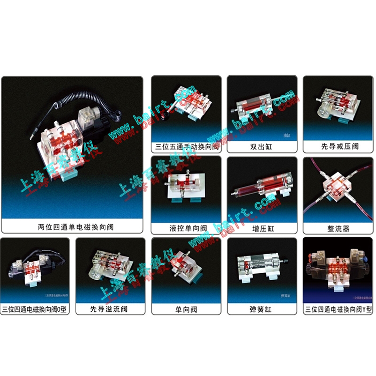
V) Enhanced configuration simulation software, achieving functional strengthening
Six), Enhanced with hydraulic simulation software, featuring virtual circuit connection and fault detection capabilities.
1. Display the flow direction of hydraulic fluid inside the hydraulic simulation pipe.
2. The electromagnet's operational indicator light
3. Hydraulic cylinders
4. Structural drawing of a three-way four-way solenoid directional valve; the valve core can switch according to the actual working position.
5. Proximity switch, capable of real-time reading the working status of the proximity switch; (As shown in the image: green indicates the electromagnet is in operation, with the corresponding PLC port outputting control signals)
6. Hydraulic Circuit Operating Principle Diagram
7. Virtual Pressure Gauge; (Parameters can be adjusted and the overflow valve controlled via computer interface, with the virtual readings displayed on the pressure gauge)
8. Pressure Gauge Virtual Readout
9. Quantitative gear pump working section
10. Hydraulic Oil Supply
11. Direct-acting pressure relief valve
12. Virtual button control panel, capable of replacing hardware PLC button signal input.
13. Hydraulic System Operating Status Sheet