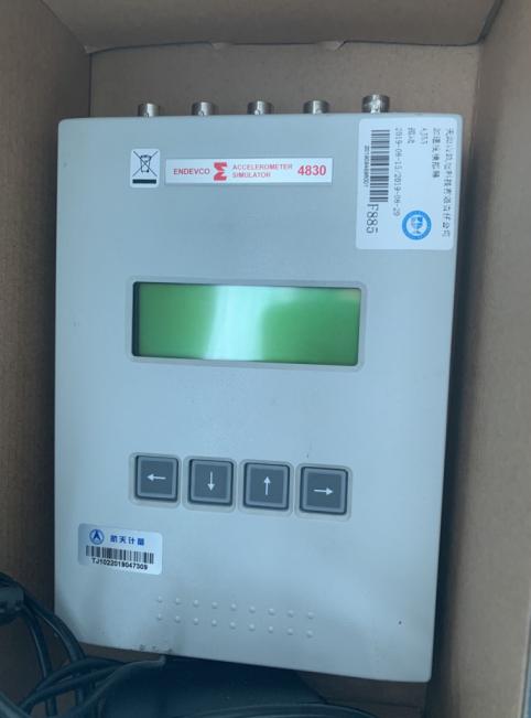


For the maintenance of the ENDEVCO Vibration Simulator 4830, the following is a systematic troubleshooting and repair guide covering common issues and solutions:
1. Preliminary inspection
Power and Connectivity
Confirm stable power input (check if the voltage meets the equipment requirements, such as ±15VDC).
Inspect all cables (power cables, signal cables, ground cables) for integrity; ensure interfaces are not loose or oxidized.
Test the auxiliary power source (such as battery-powered) for proper operation.
Appearance inspection
Inspect the equipment housing for any physical damage (drops, impact marks).
Inspect for any burnt components, capacitor bulging, or solder joint detachment on the internal circuit board.
2. Common Faults and Repair Procedures
# A. No output signal
Possible Causes
Power module failure
Signal Amplifier Damage
Sensor connection anomaly
Solution
1. Measure the output voltage of the power module with a multimeter (e.g., ±15V).
2. Check the input/output signals of the signal amplifier IC (e.g., OPA541) (requires an oscilloscope).
3. Re-plug the sensor connector, clean the contacts, or test with a spare sensor.
# B. Excessive Signal-to-Noise Ratio
Possible Causes
Poor grounding (ground loop interference)
Electromagnetic Interference (from nearby motors, inverters)
Sensor aging
Solution
Ensure equipment is grounded at a single point with ground wire resistance <1Ω.
Stay away from sources of interference or use shielded cables.
3. Compare test the new sensor to confirm if the issue is sensor-related.
# C. Unstable Vibration Frequency
Possible Causes
Control circuit failure (such as abnormal DSP or FPGA chip)
Mechanical component wear (bearings, belts)
Solution
1. Restart the equipment and observe if it recovers (temporary software fault).
2. Check the firmware version of the control panel and upgrade if necessary (contact the manufacturer for firmware).
3. Manually rotate mechanical components to check for any binding or unusual sounds.
3. Advanced Diagnostic Tools
Essential Tools
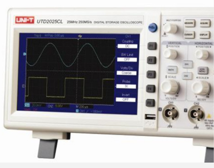
Oscilloscope (analyzes signal waveforms)
Spectrum Analyzer (Identifies Noise Frequency Components)
Multimeter (for measuring voltage/resistance)
Key Test Points
Power module output terminal
Amplifier Input/Output Terminals
Sensor feedback signal (e.g., IEPE interface)
4. Suggested Spare Parts Replacement
Parts List for Vulnerable Components
Power supply filter capacitor (e.g., 1000μF/25V)
Power Amplifier IC (Model Refer to Manual)
Sensor Cable (High Frequency Shielded Cable)
Replacement Steps
1. Discharge after power failure (to avoid residual voltage from capacitors).
2. Weld new components using static-dissipative tools.
3. Test the static current after replacement to ensure no short circuit.
5. Manufacturer Support and Calibration
Contact ENDEVCO
Please provide the equipment serial number and a description of the fault, and apply for technical documents (such as circuit diagrams).
Calibration Service: Vibration parameters require regular calibration (recommended annually).
6. Safety Precautions
High Voltage Warning: Some circuits may contain high voltage; do not disassemble by unauthorized personnel.
Static Protection: Wear an anti-static wrist strap during maintenance.
Document the repair process: Take photos to record wire sequence and component placement to prevent incorrect assembly.
7. Post-repair testing
No-load test: Confirm stable signal output.
Load Testing: Connect to standard load (such as a vibration table of known quality) to verify amplitude/frequency response.
If the issue has not been resolved,