


Adjustable plate-type fiber bundle filter
Fiber Bundle Filter With A Adjustable Plate
One. IntroductionBrief Introduction
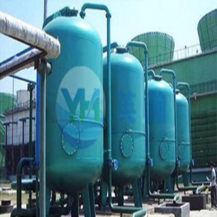
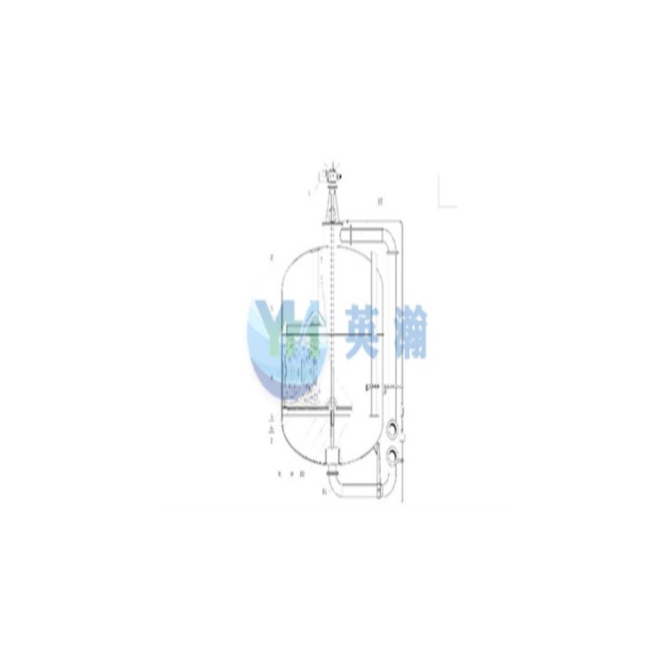
Adjustable plate fiber filter, mainly composed of a housing, a fixed support with porous plates installed within the housing, adjustable porous plates, fiber bundle filter elements fixed between the fixed support porous plates and adjustable porous plates, as well as an inlet and outlet installed on the housing. To achieve an effective cleaning, the equipment is also equipped with an air inlet and outlet for cleaning.
The fiber filter with a regulating plate is mainly composed of a shell, a fixed supporting porous plate installed in the shell and a regulating porous plate, a fiber bundle filter element fixed between the fixed supporting porous plate and the regulating porous plate, and an inlet and an outlet installed on the shell. In order to obtain a good cleaning effect, the equipment is also provided with a cleaning air inlet and an outlet.
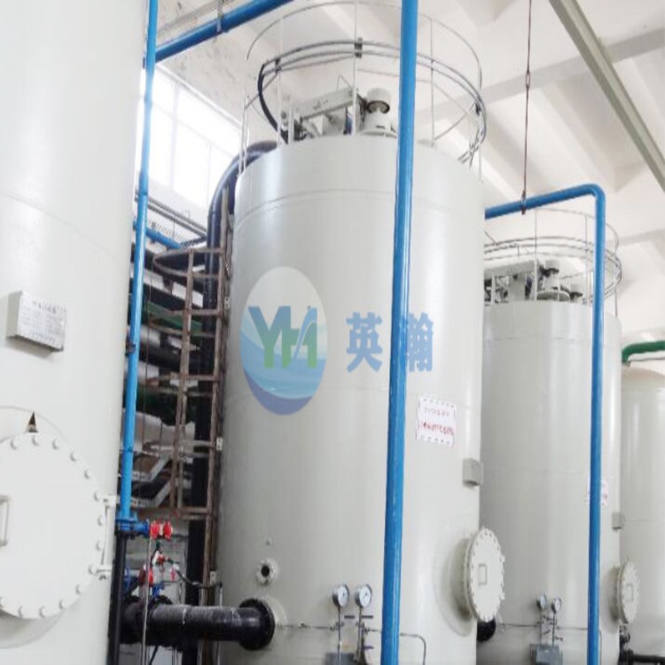
The adjustable porous plate is secured to the housing via a fixed adjustment device. One end of the fiber bundle filter element is fastened to the adjustable porous plate with a nylon rope, with the excess length of the rope equal to the expansion and contraction distance required by the fiber bundle filter element during operation and cleaning. The other end is connected to a fixed support plate for the porous plate. This type of structure, the efficient fiber filter adjustable porous plate, typically remains stationary during filter operation, unaffected by water flow and moves with the compression or relaxation of the fiber filter layer, making it less prone to wear and mechanical failure.
The adjusting porous plate is fixed on the housing with a fixing adjusting device. One end of the fiber bundle filter element is fixed on the adjusting porous plate with a high-quality nylon rope. The surplus length of the rope is equal to the stretching distance required by the fiber bundle filter element in working and cleaning, and the other end is connected to the fixing supporting porous plate. This kind of high efficiency fiber filter adjustment porous plate is usually in a static state when the filter works. It will not be affected by the water flow and move with the compression or relaxation of the fiber filter layer.
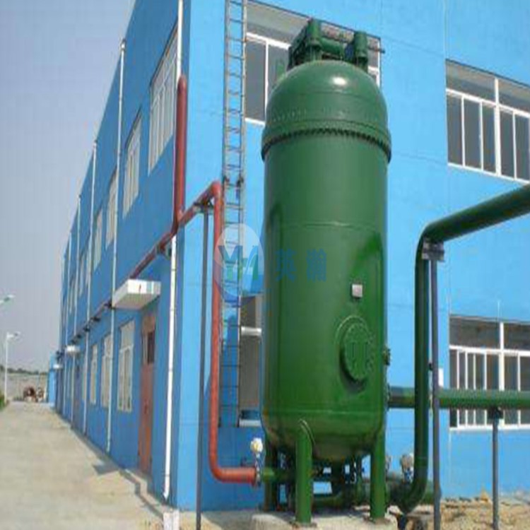
To ensure cleaning efficiency, the plate fiber bundle filter is equipped with an inverted U-shaped tube connected to the housing. A vent pipe is installed at the top of the inverted U-shaped tube, which can disrupt the siphon effect, thereby guaranteeing that the fiber filter layer remains submerged in water throughout the cleaning process, regardless of changes in the water flow rate, to maintain optimal cleaning performance.
In order to ensure the cleaning effect, the regulating plate type fiber bundle filter is set with an inverted u-shaped tube connected to the shell, and an air pipe is set at the top of the inverted u-shaped tube. The air pipe can destroy the siphon phenomenon of the inverted u-shaped tube, which can ensure that no matter how the water flow rate changes, the fiber filter layer is always immersed in water during the cleaning process to ensure the cleaning effect.
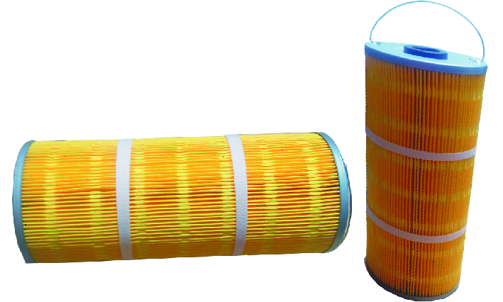
The plate-type fiber bundle filter utilizes anti-pollution fiber bundle filter media treated with special process, thus achieving excellent cleaning effects while effectively extending the operation cycle.
The adjustment plate fiber bundle filter adopts anti-pollution fiber bundle filter material after special treatment, so it can obtain good cleaning effect and prolong the operating cycle.
Two. Adjustable Plate-type Fiber Filter Specification Performance TableAdjustment plate type fiber filter specification table
Equipment Specifications and Model model number | PAF800 | PAF 1000 | PAF 1500 | PAF 2000 | PAF 2500 | PAF 3000 |
Equipment Diameter (:)mm) Equipment diameter | 800 | 1000 | 1500 | 2000 | 2500 | 3000 |
Trafficm3/h) maximum flow | 15 | 20 | 49 | 91 | 149 | 210 |
Filtering Aream2) the filter area | 0.5 | 0.78 | 1.77 | 3.14 | 4.9 | 7.06 |
Filtering Speedm/h) filtration velocity | 20~30 | |||||
Filter Layer Heightm) filter layer height | / | |||||
Operating PressureMpa) operating pressure | 0.6 | |||||
Wastewater Trapping Capacitykg/m3) sewage removal capacity | 10~15 | |||||
Pre-filter Water Quality pre-filtration water quality | Suspended Solids suspended solids(mg/L) | 20 | ||||
Turbidity turbidity(NTU) | 20 | |||||
Filtered Water Quality filtered water quality | Suspended Solids suspended solids(mg/L) | ≤2~5 | ||||
Turbidity turbidity(NTU) | ≤2~5 | |||||
Equipment Reference Weight:≈t) reference weight of equipment | 1.6 | 3.0 | 4.2 | 5.8 | 7.3 | 9.5 |
Note: The equipment specifications in the table are for reference only; the actual specifications should be based on the signed design drawings by both parties. Note: the equipment specifications in the table are for reference only, and shall be subject to the design drawing signed by both parties. For detailed information, please contact our company for acquisition. Please contact us for further information.
| ||||||