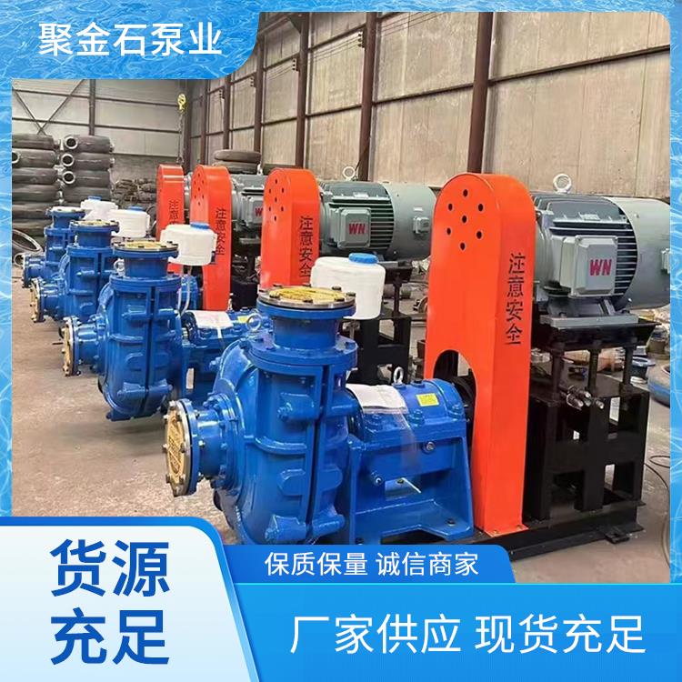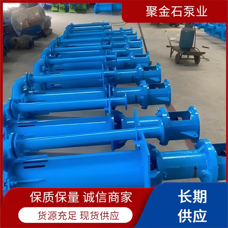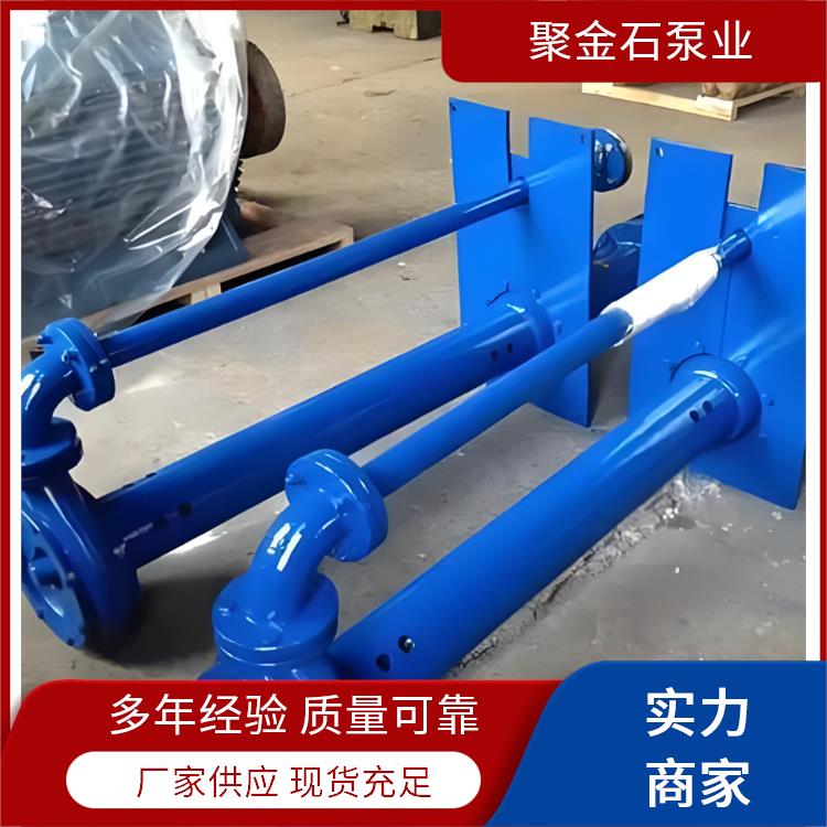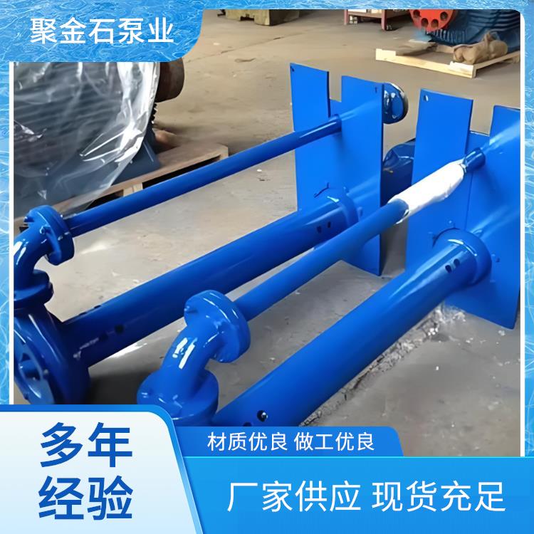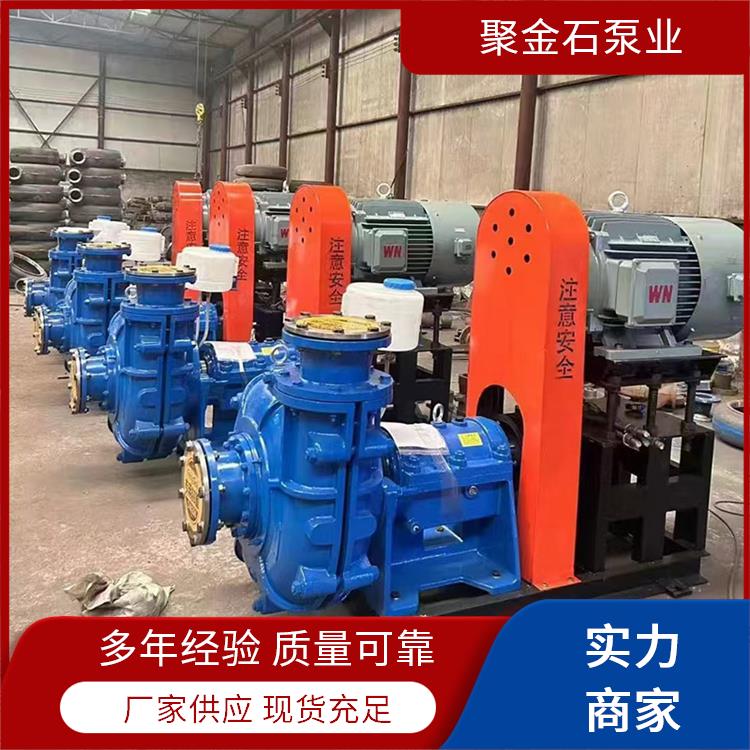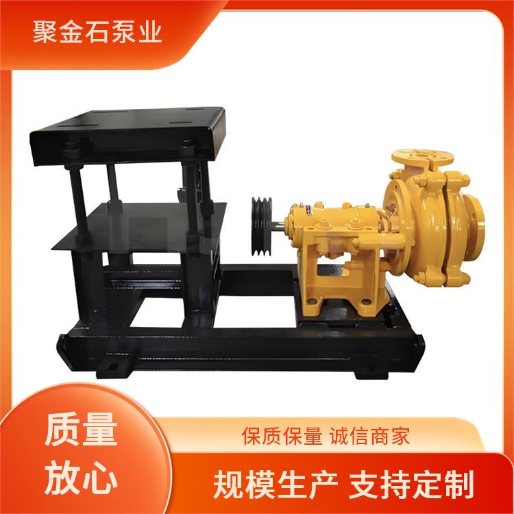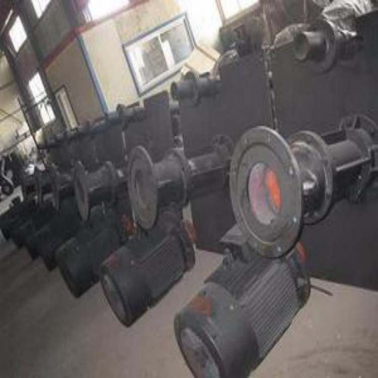


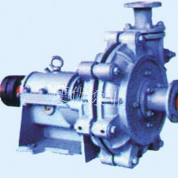
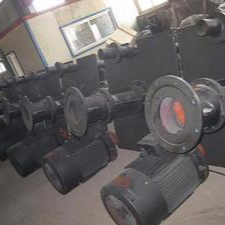
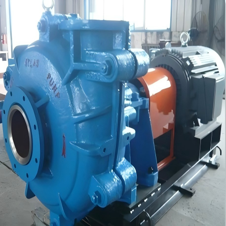
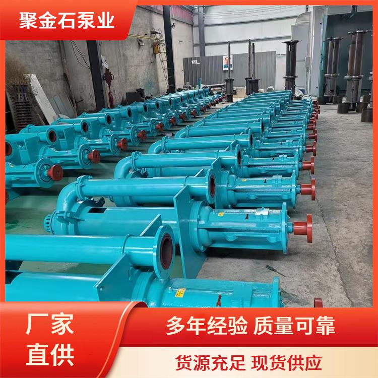


Product Name: ZJL(YW, YZ) Submerged Slurry Pumps
Product Categories: Submerged Slurry Pumps Series
I. Overview
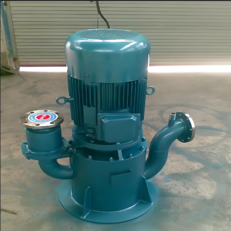
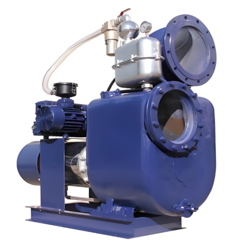
The YW type submersible pump features a vertical single-stage single-suction centrifugal pump structure. This series of pumps has semi-open impellers with mixing blades extended on the suction side of the impeller, and cutting tools for粉碎 fiber weeds are installed on the front cover. During operation, it achieves recirculation mixing, mechanical crushing, and prevents clogging.
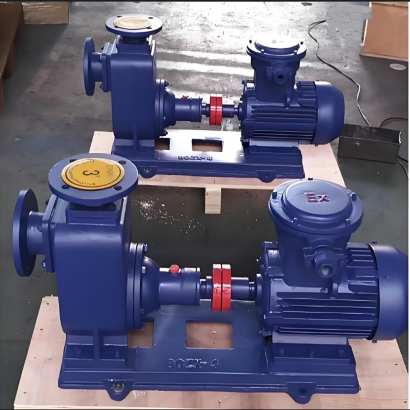
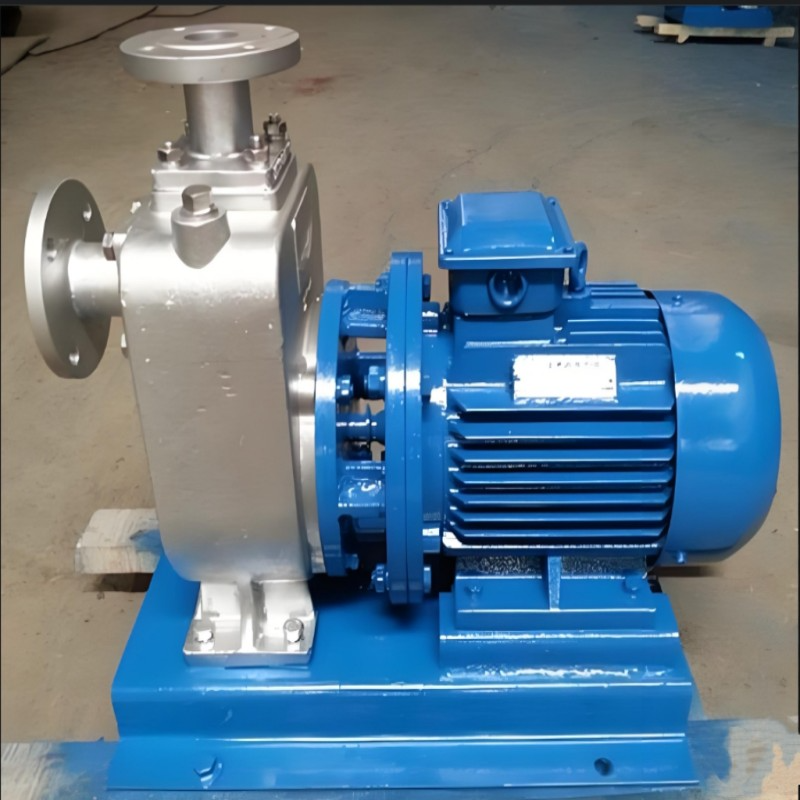
2) The YZ type submerged sludge pump features a vertical single-stage single-suction cantilever centrifugal pump structure. The impeller is a semi-open impeller, with mixing blades extending at the suction edge of the impeller.
Two series of pumps are mainly used for industries such as environmental protection, municipal engineering, thermal power plants, coal gasification plants, oil refineries, steel mills, mining, papermaking, cement plants, food factories, dyeing and printing, and for suction of thick liquids, heavy oil, oil sludge, muddy water, slurry, grout, flowing sand, and flowing sludge in urban sewage channels. They can also be used in chemical and pharmaceutical industries for suction of fluids containing mud, sand, and sludge as well as corrosive liquids. The yw type is also suitable for suction of human and animal fecal wastewater.
3) Model Significance: 80YW80-20A
YW - Submerged Multi-Use Sewage Pump
80 - Pump outlet diameter (mm)
80 - Pump Design Point Flow Rate (m³/h)
20 - Design Head of Pump (m)
A - First cut impeller
80YZ80-20A
YZ - Submerged Slurry Pump
80 - Pump outlet diameter (mm)
80 - Design Flow Rate of the Pump (m³/h)
20 - Pump Design Head (m)
A - Indicates the first cutting of the impeller
4) Pump Drive Method: The pump is connected to the motor via an elastic coupling, and the pump rotates clockwise when viewed from the direction of the prime mover.
II. Structural Description
The YW type pump is a single-stage, single-suction, submersible centrifugal pump. It connects the hydraulic components of the pump with the bearing housing and support plate using a connecting pipe. The liquid is discharged through the outlet pipe components. The impeller features a semi-open impeller with mixing blades extended at the impeller blade inlet, capable of conveying media containing particles. The maximum submersion depth of this pump is
4.5m, When the liquid submergence length exceeds 1.5m, a spool structure must be used, with rolling bearings (grease-lubricated) installed near the spool. The pump's lowest rolling bearing is isolated from the liquid surface by a mechanical seal. It does not come into contact with the fluid. The pump bearings have sufficient rigidity to ensure smooth operation; if used in deep wells, an additional suction pipe may be installed (as noted in the contract). 2. The YZ-type pump is a single-stage, single-suction cantilever structure, connected by bearing brackets, support brackets, and connecting pipes to the hydraulic components of the pump. The fluid is discharged through the discharge pipe component. The pump impeller features a semi-open impeller with agitator blades at the impeller blade extension. The main characteristic of this pump is that the pump shaft below the liquid level has enough rigidity, with no bearings between the impeller and the pump housing, and without a shaft seal, allowing the conveyance of media containing large concentrations of solid particles. The pump can be submerged for lengths between 800-1800mm, and an intake pipe can be included if needed. The shaft seal is designed to run the submersible pump in the liquid, without a shaft seal; the transmission is driven by a vertical motor mounted on motor supports and brackets, connected to the pump via a coupling.
Section 3: Product Features:


5. Assembly and Disassembly
The assembly sequence of the YW type submersible pump involves installing the bearings separately within the bearing housing.
Seal the oil seal gaskets separately inside the bearing housing and the bearing end cover.
Install mechanical seal into the shaft seal housing
Install the bearing end cover near the mechanical seal on the shaft, fit the O-ring, sleeve, and the bottom bearing housing with the assembled bearing onto the shaft, tighten the bearing end cover with bolts, and secure the connecting pipe and shaft seal on the top and bottom ends of the bottom bearing housing with bolts. Mount the bearing end cover on the intermediate bearing housing, tighten with bolts, insert keys into the shaft, fit the coupling into the shaft, insert keys into the top shaft, and fit into the coupling sleeve. Install the upper connecting pipe on the intermediate bearing, tighten with bolts, place the assembled components on the support plate, and mount the upper bearing housing on the support plate, securing with bolts, and then install the upper bearing end cover.
Install the pump cover onto the shaft seal housing and tighten with bolts. Insert the impeller key into the shaft, then sequentially install the impeller, lock washer, and secure with impeller nuts. Mount the pump body onto the pump cover and fasten with bolts. Attach the front cover and secure it to the pump body with bolts.
Install the coupling component at the top of the shaft, and securely fasten the motor coupling to the motor shaft end with set screws, ensuring a firm connection between the motor and the motor base.
Assemble the asbestos gasket, elbow, and discharge pipe components in sequence from the pump outlet, and secure them to the support plate.
2. The assembly sequence for the YZ type submersible pump involves installing the bearings separately into the bearing box and bearing housing.
Install felt washers on the bearing end caps A, B, and the bearing box.
Install bearing end caps B and C onto the bearing housing and secure with bolts.
Thread the bearing box filled with bearings onto the shaft, tighten the locknut, and secure the bearing end cover to the bearing box.
Insert the shaft into the bearing, secure with bolts, tighten the adjustment screw, and mount the bearing housing on the support bracket. Fit the water shield at the appropriate position on the lower bearing.
Secure the union pipe to the bearing housing, install the pump cover below the union pipe, mount the impeller at the bottom of the shaft and tighten it, then install the pump body front cover in sequence and bolt it down. Adjust the gap between the impeller and the front cover using the adjustment screw at the bearing box (keep it between 1-1.5mm), and once adjusted, secure with nuts and bolts.
The motor bearing is mounted on the bracket and secured with bolts. The coupling component is installed at the top of the shaft, and the motor coupling is fastened to the motor shaft end with set screws. The motor is then mounted on the bracket and secured with bolts and nuts.
Assemble the asbestos gaskets, discharge elbow, and discharge pipe components in the order from the pump outlet, and secure them to the support bracket. Disassembly of the pump is performed in the reverse order of the above steps.
Six, Installation
Pre-installation preparation
Check for any damage to the pump motor
b. Prepare tools and lifting equipment
c. Inspect foundation as per drawing.
2. Install the pump support bracket onto the container and tighten the bolts (pre-set anchor bolts if it's a cement well tank).
Section 7: Start-up and Shutdown
Check if the pump's installation foundation is stable and if all bolts on the components are tightened.
Check if the pump's axial clearance has been adjusted properly (no friction sound when the coupling is moved).
Oil cup injects calcium-based butter
Check the motor's rotation direction for correctness
Start the motor, open the pressure gauge valve, and adjust the gate valve opening to the required range when the pump is operating at full speed.
When the pump stops operating, the motor should be turned off first, followed by closing the pressure gauge valve.
When the pump is to be shut down for an extended period, it should be disassembled, cleaned thoroughly, coated with anti-rust oil, and stored properly.
Eight, Operation
Pay attention to the pump bearing temperature; it should not exceed 35℃ above the ambient temperature but should not be greater than 75℃ at its highest.
Ensure the oil cup is filled with calcium-based grease to ensure proper lubrication of the bearings.
The motor bearing grease in the oil cup should be changed within the first month of operation or after 100 hours of runtime. Thereafter, it should be replaced every 2000 operating hours.
Regularly inspect the elastic coupling and monitor the motor bearing temperature rise.
During operation, if any noise or unusual sounds are detected, stop immediately for inspection.
Pumps should undergo periodic inspections every 2000 operating hours. The wear between the impeller and pump housing (or cover) should not be excessive; the maximum gap should not exceed 1.5 millimeters. If it does, a replacement impeller or front cover can be installed.