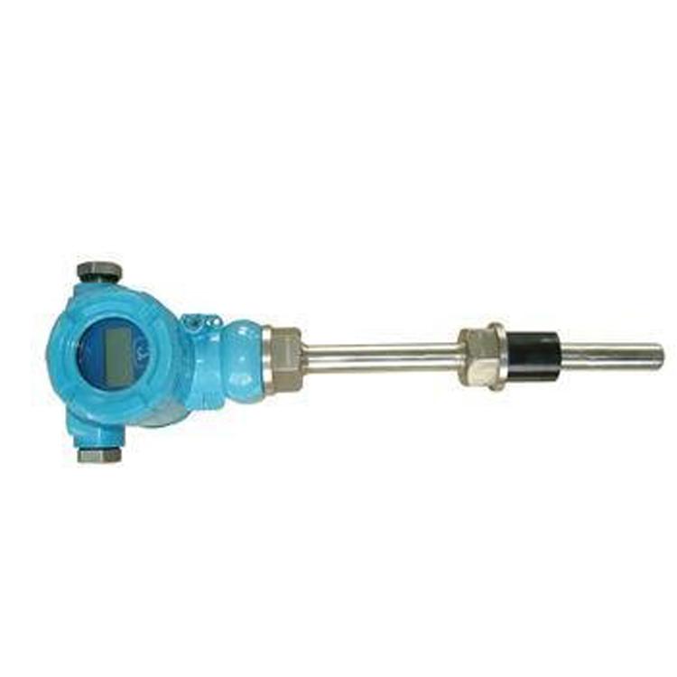


Intrinsically Safe Thermistor AssemblyIntroduction
Integrally-mounted explosion-proof resistance thermometers are commonly used with display meters, recording meters, electronic computers, etc., and provide an output of 4-20mA. They directly measure the temperature of liquid, steam, and gas mediums as well as solid surfaces in the range of 0-1800°C across various production processes.
Key Features
Two-wire output of 4-20mA, with strong anti-interference capability.
Save on compensation wire and temperature transmitter installation costs.
Wide measurement range;
Automatic temperature compensation on the cold side, non-linear correction circuit.
Operating Principle
Integral explosion-proof thermoresistorUsing the gap explosion-proof principle, when an explosion occurs inside the cavity, it can extinguish and cool the fire through the joint surface gap, preventing the temperature of the flame after the explosion from reaching outside the cavity, thus enabling temperature measurement. The thermoelectric potential (resistance) produced by the thermocouple (resistor) generates an unbalanced signal through the bridge of the temperature transmitter, which is then amplified and converted into a 4-20mA DC signal for the working instrument. The working instrument displays the corresponding temperature value.
Technical Specifications
Implementation Standard
IEC584 IEC1515 IEC751 JB/T5518-91 JB/T7391-94
Temperature Range and Allowable DeviationThermocouple)
Model | Pitch number | Allowable Tolerance & Grade of Raw Material | |||
I Grade | II Grade | ||||
Tolerance range | Temperature Range: ℃ | Tolerance value | Temperature Range: °C | ||
WRNB | K | ±1.5℃ | -40~+375 | ±2.5℃ | -40~+333 |
±0.004│t│ | 375~1000 | ±0.0075│t│ | 333~1200 | ||
WRMB | N | ±1.5℃ | -40~+375 | ±2.5℃ | -40~+333 |
±0.004│t│ | 375~1000 | ±0.0075│t│ | 333~1200 | ||
WREB | E | ±1.5℃ | -40~+375 | ±1.5℃ | -40~+333 |
±0.004│t│ | 375~800 | ±0.004│t│ | 333~900 | ||
WRFB | J | ±1.5℃ | -40~+375 | ±1.5℃ | -40~+333 |
±0.004│t│ | 375~750 | ±0.004│t│ | 333~750 | ||
WRCB | T | ±1.5℃ | -40-~+125 | ±1℃ | -40~+333 |
±0.004│t│ | 125~350 | ±0.0075│t│ | 133~350 | ||
WRPB | S | ±1℃ | 0~+1100 | ±2.5℃ | 0~600 |
±[1+0.003(t-1100)] | 1100~1600 | ±0.0025│t│ | 600~1600 | ||
Note: t represents the absolute value of the measured temperature of the thermosensitive element.
Temperature Measurement Range and Tolerance (Thermistor)
Model | Pitch number | Temperature Range: °C | Precision Grade | Permitted deviation |
WZPB | Pt100 | -200~+500 | Grade A | ±(0.15+0.002|t|) |
Grade B | ±(0.30+0.005|t|) | |||
WZCB | Cu50 | -50~+100 | - | ±(0.30+0.006|t|) |
Cu100 |
Note: t represents the absolute value of the measured temperature of the thermosensitive element.
Ex-proof rating:
Airtight: dIIBT4, dIICT5, dIICT6
Intrinsic Safety Type: iaIICT6
Other Parameters
Output Signal: 4-20mA, Load Resistance: 250Ω, Transmission Wire Resistance: 100Ω
Output Method: Binary System
Tolerance Grades: 0.1; 0.2; 0.5
Power Supply: 24V.DC ±10%
Protection Level: IP65
Thermal Response Time
When there is a step change in temperature, the current output signal of the instrument changes to 50% of the step change required time, usually represented as τ0.5. If the step response stability time of the temperature transmitter does not exceed one-fifth of the thermal response stability time τ0.5 of the thermocouple (resistor), then the thermal response time of the thermocouple (resistor) is used as the instrument's thermal response time.
When the settling time of the temperature transmitter's step response does not exceed half of the thermocouple (resistance) thermal response settling time τ0.5, then use the temperature transmitter's thermal response time as the instrument's thermal response time.