


Product Description
Brand He Guo Group Model CFW-60/0.8
Material: Stainless Steel, Diameter: 2916mm
Application Range -162℃ Volume 60000L
Heat Exchange Area - See drawing sqm, Ambient Temperature - See drawing °C
Wall Thickness: 8mm, Outer Dimensions: φ2916*14929mm
Origin: Shandong Heze
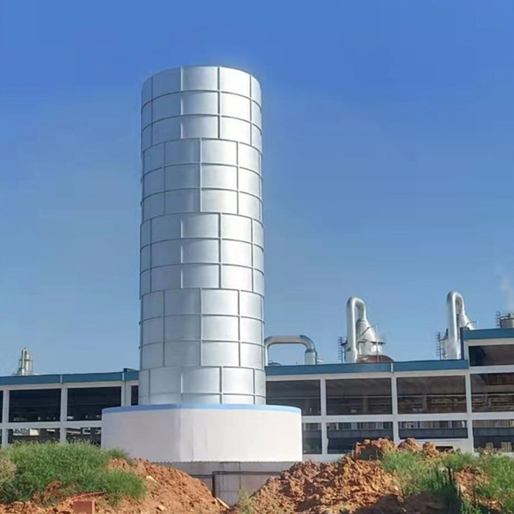
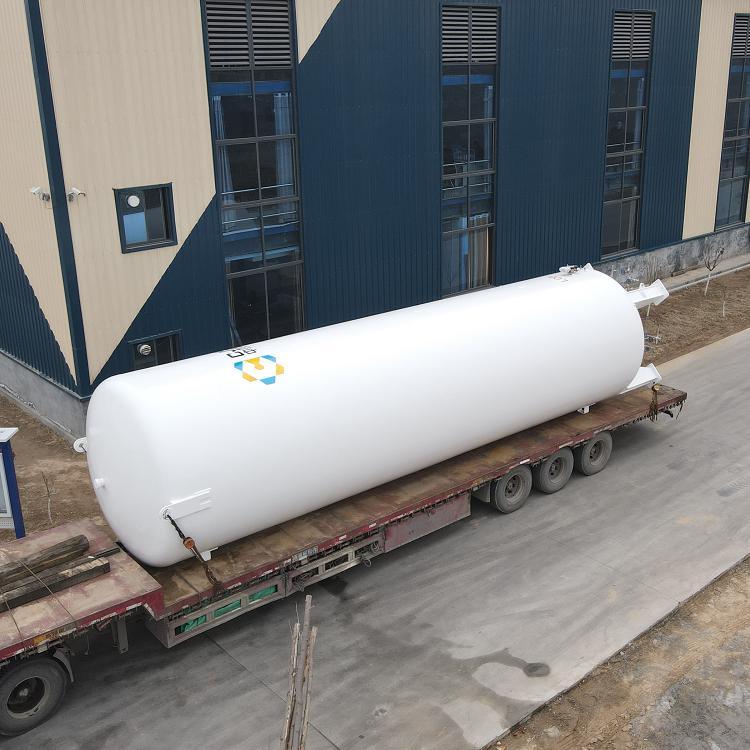
Jiangxi 60-cubic-meter LNG Storage Tank, Hunan 100-cubic-meter Natural Gas Storage Tank, 30-cubic-meter LNG Storage Tank Price

1.2 Pre-Pressure Regulation Preparation
1.2.1 Tool Preparation: Explosion-proof wrench, two pairs of gloves, and two sets of protective gear.
1.2.2 Work Preparation
Wear personal protective equipment, including antistatic suits, static-free shoes, safety helmets, etc.
Ensure that static-prone devices like smartphones and computers have been placed in a safe area, and check if the surrounding environment around the work area is secure and meets the operational requirements.
Before entering, rub hands on the static discharge device to release static electricity.
Check if all pressure regulating tools, such as explosion-proof wrenches, are carried.
Check that the tank's pressure gauge, level gauge, thermometer, combustible gas detector, and safety valve are all functioning normally.
Inspect pipeline valves, pressure gauges, and safety valves to ensure they are in normal working condition.
(7) Prepare all explosion-proof tools
1.2.3 LNG Storage Tank Gas Supply Process:
All valves on the tanks to be pressurized, except for the root valve and the emergency shutdown valve, are in the closed position.
Open the lower tank inlet valve and the booster liquid and vapor phase valves, check that both valves of the booster vaporizer are in the open position.
Open the low-temperature cutoff valve before the gasifier, the at-room-temperature flanged ball valve after the gasifier, and all valves in the pressure regulating system that need to be opened.
When the gas supply rate is less than 1000-2000 Nm3/h, one storage tank is sufficient to meet the gas supply requirements.
5. Liquid Output:
5.1 When the tank pressure reaches more than 0.15MPa above the outlet pressure, gradually open the liquid outlet valve to initiate the gas supply operation.
5.2 Record the liquid storage tank number and the start of gas supply time.
5.3 Pay close attention to the liquid level, pressure changes, and flow and pressure variations at the exit of the storage tank during gas supply.
1.2.4 Operation Procedure for Self-pressurization of LNG Tanks
Upon manual operation, open the valves: the boost liquid phase valve, the boost gas phase bypass valve, and the vaporizer inlet valve, allowing LNG to flow directly into the self-boosting vaporizer, where it is vaporized and then enters the LNG storage tank. At this point, closely monitor the pressure; close the boost liquid phase valve once the pressure in the LNG storage tank reaches the required level.
Cautionary Notes:
During LNG tank operation, the liquid level must be maintained at ≤90% for the upper limit and ≥15% for the lower limit. (2) When manually operating the self-pressurization system, it is strictly prohibited to leave the site unattended.
(3) When the self-pressurizing system is in operation, the pressure-reducing system should be in the off state.
Cautionary Notes:
During the operation of the LNG tank, the liquid level must be ≥15%.
(2) No one is allowed to leave the scene during manual operation.
1.2.5 Risk Analysis and Countermeasures
During LNG tanker loading and unloading, operators should wear face masks, antistatic work clothes, and antifreeze gloves, etc.
During LNG tanker unloading, the vehicle must not be moved to prevent the disconnection of the loading and unloading hoses, which could lead to a large LNG leak.
When LNG is inside the pipeline, both ends' valves cannot be closed simultaneously.
Keep hands and feet off low-temperature pipelines and equipment.
Under no circumstances shall moisture, oil, mechanical impurities, etc., enter the pipeline to avoid blockages.
No striking, baking with fire, or spraying water on the frozen areas.
To ensure the safety of the working environment, operators must wear protective gear properly. Static electricity from the human body must be neutralized before entering the station. Open flames are strictly prohibited within the station's operational area, as well as the use of non-explosion-proof tools and electronic devices.
Strictly follow the operation ticket system, executing according to the steps outlined on the ticket. Field operators must consist of at least two people: one to operate and one to supervise, ensuring operational safety.
Conduct safety training prior to operation, implement on-site safety precautions effectively. In case of danger, know how to evacuate and control the situation.
1.2.6 Procedure for Maintenance and Care of LNG Storage Tanks
Operation technicians at Liquefied Natural Gas (LNG) stations must be familiar with the structure and principles of the storage tanks and strictly adhere to the operational procedures for LNG-related activities.
LNG operation technicians must be familiar with the performance and principles of the tank accessories (pressure gauges, level indicators, temperature gauges, vacuum test valves).
The outer shell of the Liquefied Natural Gas storage tank is an externally pressurized vacuum vessel; welding operations are strictly prohibited under negative pressure. 4. Regularly inspect the outer shell of the storage tank, observing for any signs of icing or frost. Upon discovering icing or frost, report it immediately to the on-duty supervisor and station master. The on-duty supervisor or station master should immediately contact the manufacturer to investigate and address the cause. Pay close attention to the changes in icing or frost during the handling process. If there is a tendency for the incident to escalate, immediately perform tank draining or cease filling operations, and close the relevant emergency cut-off valves at the inlets and outlets.
Regularly inspect the storage tank's connecting pipes and valves, observe for any frosting, and report any issues to the on-duty supervisor immediately. The supervisor will then arrange for personnel to address the situation.
Regularly inspect the pressure gauge, level gauge, and thermometer of the storage tank to ensure the displayed values are normal. 7. Regularly check the sealing performance and operation of the valves connected to the tank to ensure proper functioning.
Regularly inspect safety valves, pressure gauges, level gauges, and thermometers in accordance with regulations to ensure proper operation and promptly update the equipment inventory records.
Regularly carry out anti-corrosion treatment on the outer shell of storage tanks and perform external cleaning and maintenance on the pressure gauges, level gauges, and thermometers of the tanks.
Regularly perform rust removal and anti-corrosion treatment on the easy-to-rust areas of storage tanks, such as pressure and level control instruments' three-way valves.
11. Conduct annual or on-demand vacuum level checks on the storage tank to monitor its operational status.

Jiangxi 60 cubic meter LNG storage tank, Hunan 100 cubic meter natural gas storage tank, 30 cubic meter LNG storage tank price
Product Description
Brand Hoogou Group Model CFW-60/0.8
Material: Stainless Steel, Diameter: 2916mm
Application Range -162℃ Volume 60000L
Heat Exchange Area - See drawing in square meters (㎡) | Ambient Temperature - See drawing in degrees Celsius (℃)
Wall Thickness: 8mm, Outer Dimensions: φ2916*14929mm
Origin: Shandong Heze
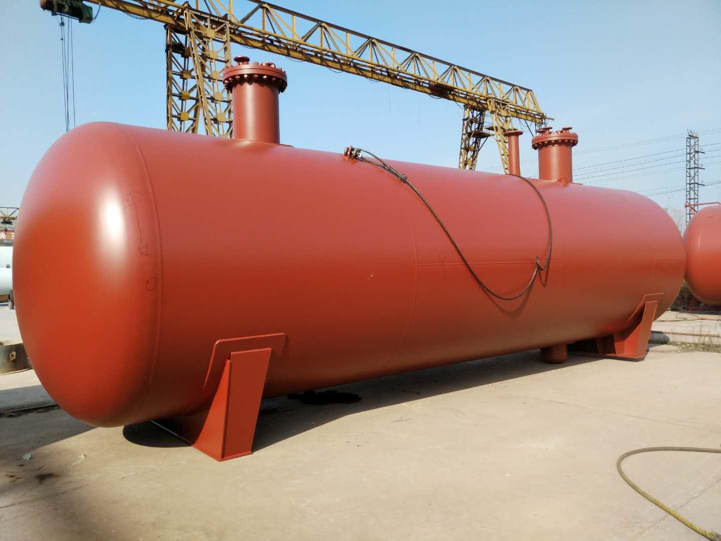
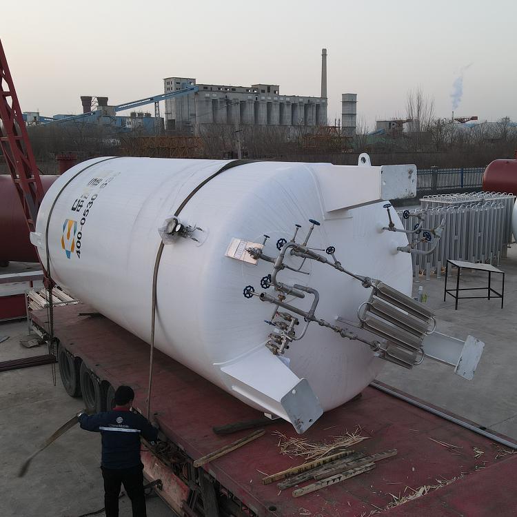
LNG Tank, Low-Temperature Natural Gas Tank, 60 Cubic Meter LNG Tank, Imported Paint from the USA, High Vacuum Level
1. Preparatory Work
Tanks should undergo airtightness tests, blow-off treatment, and valve and instrument inspections prior to use.
1.1. Airtightness Test
The tank should undergo a system tightness test after installation is complete or the inner cylinder returns to normal temperature, prior to filling with low-temperature liquids. The test pressure should be the maximum working pressure of the tank, using oil-free dry air or dry nitrogen as the test gas. The duration of the test depends on the tank size but must not be less than 4 hours.
1.2 Blowing Treatment
After the airtightness test passes, the inner tank system must be purged with oil-free dry air or dry nitrogen to remove moisture. After purging with dry air or nitrogen, the product gas should also be used for purging. During purging, gases lighter than air are added from the top, through the vent valve, and removed from the bottom via the liquid inlet and outlet valves. To accelerate the removal of moisture inside the tank, the purge gas can be heated to 80-100°C. Each pipe and valve should be purged individually, especially the level gauge and pressure gauge, which should have the gas expelled from the joints to remove water from the pipes. Liquid filling can only begin once the dew point of the gas expelled from the inner tank system meets the required specifications.
1.3 Valve Instrument Inspection
Before filling with low-temperature liquid, ensure that the valves are in the correct position, the gauges are responsive and reliable, and the liquid level gauge connections are unobstructed.
2. Filling: divided into initial filling and top-up filling.
2.1 Initial Filling (referring to filling while the inner cylinder is in a heated state). The steps are as follows:
2.1.1 Connect the filling pipeline.
2.1.2 Perform blowout on the filling pipeline (should be done before each filling), and before the upper liquid inlet and outlet valves are opened, place a small amount of liquid into the output pipeline from the liquid source valve. Simultaneously, open the pipeline residual liquid drain valve and clean the pipeline to remove moisture and dust impurities from within.
2.1.3 Open the internal pipe vent valve and pressure gauge valve, and simultaneously start the level gauge.
2.1.4 Open the upper liquid inlet valve, allowing liquid to enter from the top. Since the inner cylinder is in a hot state, the upper liquid inlet valve should be slightly open to allow the pipeline and inner cylinder to gradually cool to the temperature of the liquid being filled. Once the inner cylinder's vent valve stabilizes and exhausts, you can open the upper liquid inlet valve wider and increase the filling speed.
2.1.5 When the liquid level indicator indicates a liquid level, open the liquid inlet and outlet valves, and close the upper liquid inlet valve to switch from upper to lower liquid inlet.
2.1.6 When the liquid fills the indicator valve (already opened) and sprays out, it indicates that the storage tank is full of liquid. Immediately close the liquid inlet and outlet valves, stop filling, and open the pipeline residual liquid discharge valve to expel the remaining gas and liquid in the filling pipeline.
2.1.7 Remove the filling pipeline upon completion of filling.
2.2. Fill-in Liquid (referring to the inner cylinder already having low-temperature liquid, no longer requiring cooling of the inner cylinder)
2.2.1 Similar to the initial filling, the difference is that the filling quantity can be increased from the start, and close attention must be paid to pressure changes during the filling process. If liquid is directly introduced through the liquid进出口 valves, when the pressure rises significantly, to reduce the pressure, switch from bottom (lower) filling to top (upper) filling.
2.2.2 Additionally, from a pressure perspective, they can be categorized into atmospheric filling and pressure-filled filling.
2.2.3 During the atmospheric filling process, the inner cylinder drain valve remains open, allowing the inner cylinder to be in communication with the atmosphere, hence the term "atmospheric filling."
During pressure filling, the vent valve is closed, and the pressure inside the tank is higher than atmospheric pressure, hence the term "pressure filling." However, the working pressure of the storage tank should be greater than 2 Kg/cm2. Whether at standard atmospheric pressure or engineering atmospheric pressure, 1 Kg/cm2 = 98100 Pa = 0.0981 MPa.
3. Boosted Pressure
When transferring the liquid in the storage tank to other storage tanks or for vaporization use, it is necessary to increase the internal cylinder pressure. The increase in pressure should be determined based on the user's actual requirements but must not exceed the maximum working pressure of the storage tank.
Its boost program is:
3.1 Check if the pressure gauge and level gauge are in working condition.
3.2 Ensure the gas valve is fully open.
3.3 Slowly open the turbocharger inlet valve (boost valve) to allow the liquid to vaporize in the turbocharger. If the draining speed is fast, the inner cylinder pressure will drop rapidly, and the boost valve can be opened wider. Once the pressure reaches the required working pressure, reduce or completely close the turbocharger inlet valve. At this point, the liquid inside the turbocharger will continue to evaporate until the desired pressure is reached. During the boost process, closely monitor the pressure gauge readings.
4. Liquid Discharge
Three forms of liquid effluent exist.
4.1. Carburetor Drain
Once the pressure inside the tank reaches the required level, the drain valve can be opened to supply liquid to the vaporizer, heating it up and vaporizing it for delivery to the usage site. This is the primary drainage method for tanks equipped with a vaporizer.
4.2 Liquid discharge through liquid进出口 valves
This drainage process involves supplying liquid to tank trucks or larger storage tanks through输液软管, with the operational procedures largely similar to refueling, except the liquid inlet and outlet valves have been changed from intake to drainage.
4.3 Drainage valve (also known as liquid discharge valve) or direct drainage through Dewar tube
This type of draining supplies liquid to portable small containers like Dewar flasks. Simply connect the metal flexible tube from the small container to the drain valve (or through a Dewar tube), open the liquid outlet valve, and the liquid is supplied. This draining volume is small, and for fixed storage tanks, it may not require pressurization based on specific conditions, allowing for external liquid supply.
5. Storage
Liquid storage includes two methods: atmospheric storage and pressurized storage.
5.1 Atmospheric Storage
During atmospheric storage, the vent valve on the inner cylinder is always open to allow gases to evaporate naturally and escape through the valve into the atmosphere, preventing the pressure inside the tank from rising. Since the natural evaporation is minimal, the vent valve only needs to be slightly open. (The opening should be adjusted to maintain constant pressure within the tank.)
5.2 Pressure-Containing Storage
During the pressurized storage process, the vent valve is closed as the gaseous vapor from natural evaporation remains inside the tank, causing the internal cylinder pressure to gradually increase. At this point, the pressure gauge indicates pressure, and the vent valve should be immediately opened to relieve pressure once the internal cylinder pressure reaches the working pressure.
6. Issues with simultaneous filling and draining of fluids
There are many situations that require a continuous supply of gas, and having two or more tanks meets this requirement. However, when there is only one storage tank, whether it can supply gas continuously depends on whether the tank can perform simultaneous charging and discharging. Generally, for a tanker truck to fill a fixed storage tank with liquid, simultaneous charging and discharging should meet the following conditions:
6.1 The operating pressure of fixed storage tanks should be above 0.02 Mpa.
6.2 During the liquid filling process, the upper liquid inlet valve and the liquid inlet and outlet valves should be frequently adjusted, as filling from the top can decrease the pressure inside the tank, while filling from the bottom can increase the pressure.
6.3 When filling and emptying liquids simultaneously, if the pressure requirements cannot be met by entering liquid from the bottom, you can open and adjust the size of the booster valve to maintain stable pressure within the tank.
7. Maintain
7.1 Do not tamper with the explosion-proof device of the outer cylinder or the vacuum valve; otherwise, it will damage the vacuum level of the storage tank.
7.2 Shell is subject to atmospheric pressure as an external pressure vessel; collision is strictly prohibited to prevent damage to the shell and affect the vacuum level.
The tank vacuum level should be checked every six months. To measure, simply unscrew the protective cap on the metal thermowell and insert the plug of the thermocouple vacuum gauge, then you can know the true vacuum level of the jacket.
7.3 After several years of use, the vacuum level in the tank may drop below 66.66 Pa, at which point a re-vacuuming is necessary.

LNG Tanks, Low-Temperature Natural Gas Tanks, 60 Cubic LNG Tanks, Imported Paint from the USA, High Vacuum Degree


菏泽锅炉液化天然气储罐燃气热水锅炉-专业液化天然气储罐价格-专业的液化天然气储罐制造商-菏泽锅炉液化天然气储罐燃气蒸汽锅炉