
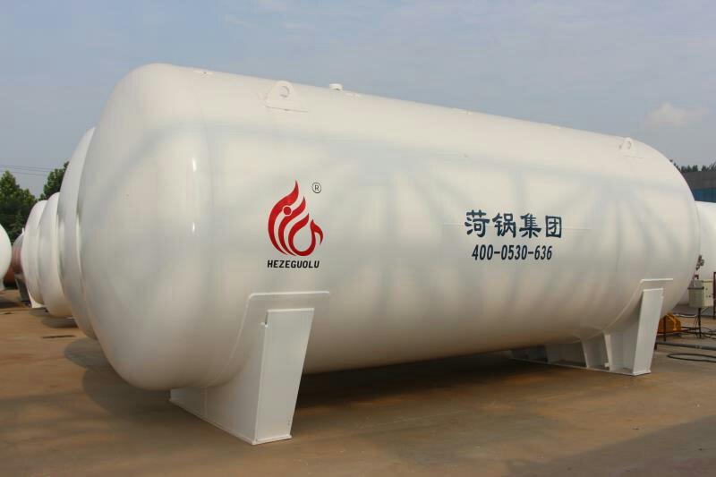
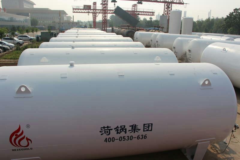


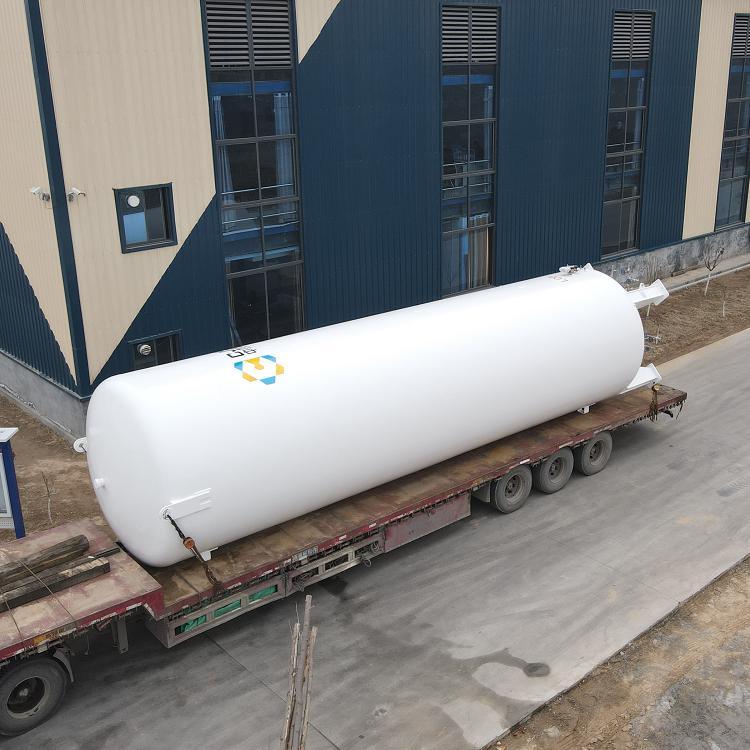

30, 60, and 100 cubic meter LNG storage tanks, LNG gasification stations, and vehicle refueling station process and equipment selection
I. LNG, CNG, LPG - Meanings
CNG: Compressed Natural Gas, which is natural gas compressed to 20MPa, is called CNG. Vehicles fueled by this stored in high-pressure cylinders are known as CNG vehicles. High-pressure cylinders stored at normal temperature: 20MPa.
LNG: Liquefied Natural Gas (LNG) is formed by cooling natural gas to -162℃. It is stored in low-temperature tanks, and cars powered by this fuel are known as LNG vehicles. Cylinders for low-pressure and low-temperature storage: 1.6 MPa.
LNG and CNG refueling, storage, and supply systems have certain differences, but natural gas ultimately enters the car engine in a gaseous state after being pressurized through a pressure regulator to 0.15 MPa for combustion and work.
LPG: Liquefied Petroleum Gas
Section 2: Applications of LNG Storage Tanks: Gasification Stations and Vehicle Fueling Stations
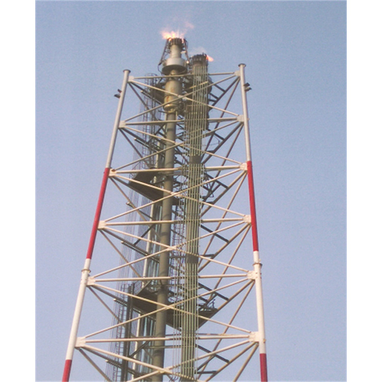
LNG Gasification Plant
(1) Peak load and load balancing for urban pipeline gas supply and accident adjustments
(2) Gas source for city municipal gas networks in areas where natural gas pipelines have not been laid.
(3) Gas sources for community supply: boiler gas and domestic gas supply
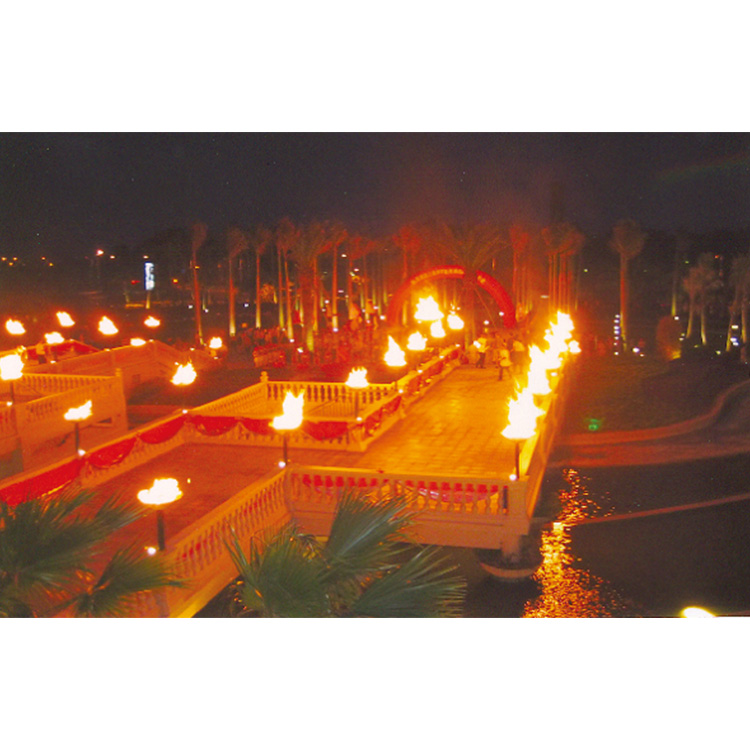
(4) Source for corporate gas supply; (Image)
2. Gasoline Stations for Vehicles: Used as Vehicle Fuel
Section 3: Types of CNG Filling Stations
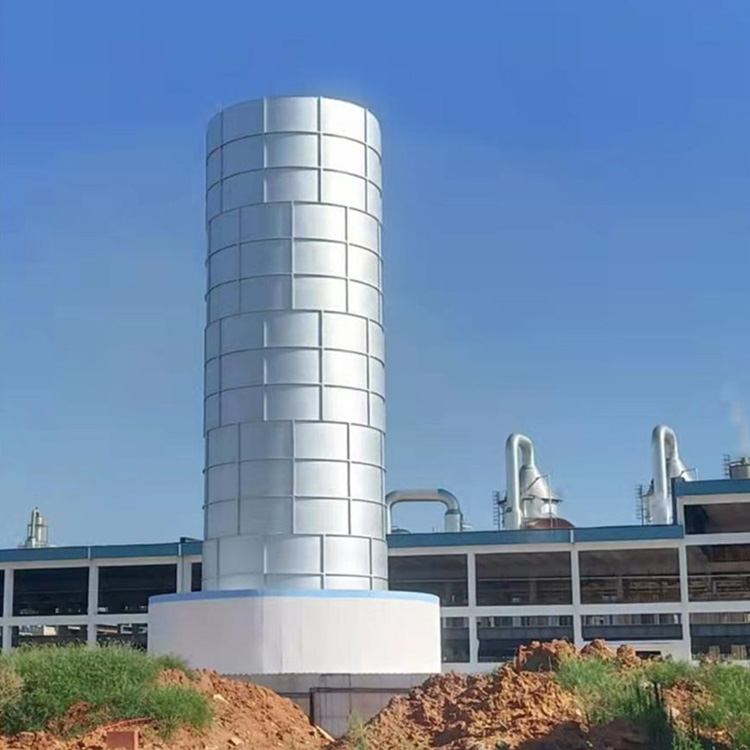
LNG Vehicle Fueling Station
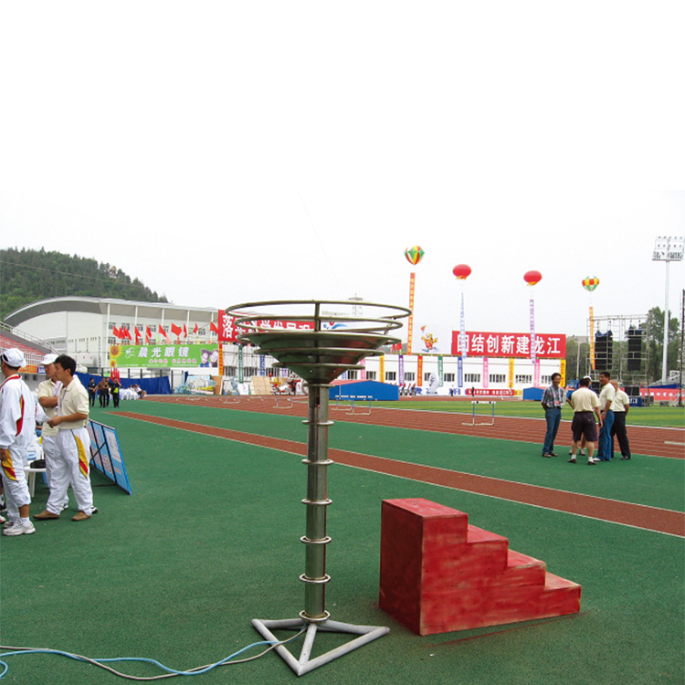
1) Conventional Station: Located at a fixed site, LNG is unloaded using unloading equipment, filled into storage tanks, and refueled into vehicles using fueling machines. (Image)
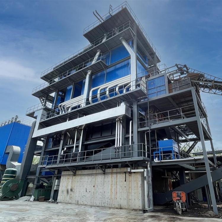
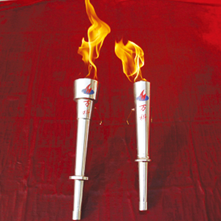
2) Skid-mounted Station: Install related equipment and facilities of a CNG station onto a truck or skid, highly integrated for easy transportation and relocation. Suitable for smaller-scale CNG stations. (Image)
2. CNG Vehicle Fueling Station
3. L-CNG Vehicle Fueling Station
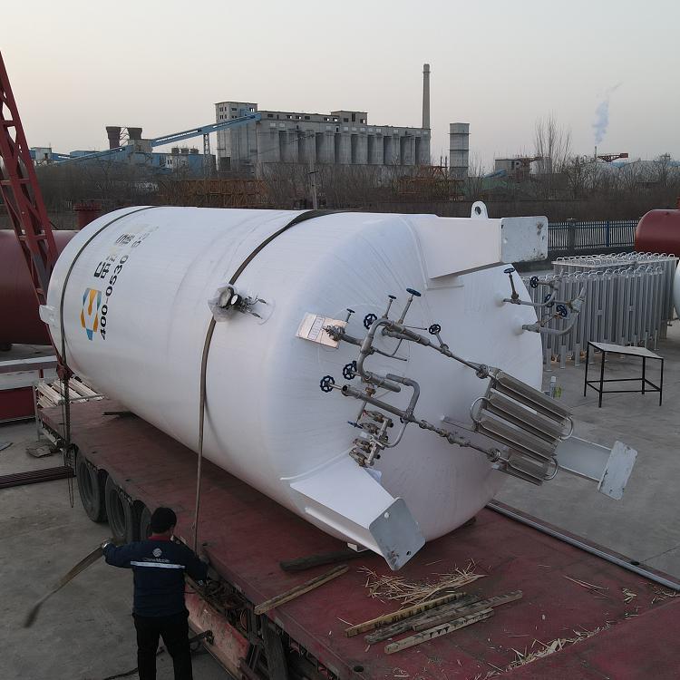
30, 60, 100 cubic LNG storage tank valves, piping, fittings
Valve Selection and Design
Process system valves should meet the pressure and flow requirements for transporting LNG, while they must also possess low-temperature performance capable of withstanding -196℃. Common LNG valves include pressure regulating valves, pressure reducing valves, emergency shutdown valves, low-temperature stop valves, safety valves, check valves, etc. The valve material is 0Cr18Ni9.
2. Pipe, fitting, and flange selection and design
Pipes with medium temperatures ≤ -20℃ are made of seamless stainless steel tubes for fluid conveyance (GB/T 14976—2002) with material 0Cr18Ni9. Fittings are all made of seamless stamped fittings with material 0Cr18Ni9 (GB/T 12459). Flanges are used with long-neck socket-welding steel pipe flanges (HG 20592) made of 0Cr18Ni9. The sealing gasket for flanges is a metal-wound type, also with material 0Cr18Ni9. Fasteners are specialized double-threaded studs and nuts, made of 0Cr18Ni9.
Process pipes with medium temperature greater than -20°C, for nominal diameter ≤ 200 mm, use seamless steel tubes for fluid conveyance (GB/T 8163) made of Grade 20 steel; for nominal diameter > 200 mm, use welded steel tubes (GB/T 3041-2001) made of Q235B steel. All pipe fittings are made of seamless forged pipe fittings (GB/T 12459) made of Grade 20 steel. Flanges are used with raised face, necked, and welded steel pipe flanges (HG 20592) made of Grade 20 steel. Flexible graphite composite gaskets (HG 20629) are used for flange sealing.
LNG process pipelines are installed using焊接connections, with only necessary flange connections. Insulation is provided for low-temperature process pipelines with polyurethane insulated pipe supports and composite polyethylene insulated pipe shells. Carbon steel process pipelines undergo corrosion protection treatment.
Section 6: Fire Protection Design for LNG Gasification Stations
The fire protection design of the LNG gasification station is in accordance with the LPG section of CB 50028 "Urban Gas Design Code." A dike area is set around the LNG storage tanks to minimize the damage to surrounding facilities in the event of an accident. Sprinkler systems are installed on the LNG storage tanks with a sprinkling intensity of 0.15 L/(s·m2). The water usage for sprinkling is calculated based on the total surface area of the storage tank on fire. Adjacent tanks within a diameter of 1.5 times that of the burning tank are calculated at 50% of their surface area. The water usage for fire hoses is selected according to GBJ 16 "Building Design Fire Protection Code" (2001 edition) and GB 50028 "Urban Gas Design Code" (2002 edition).