


Carbon Dioxide Storage Tank
1 Overview
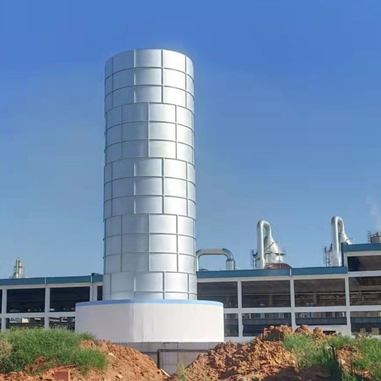
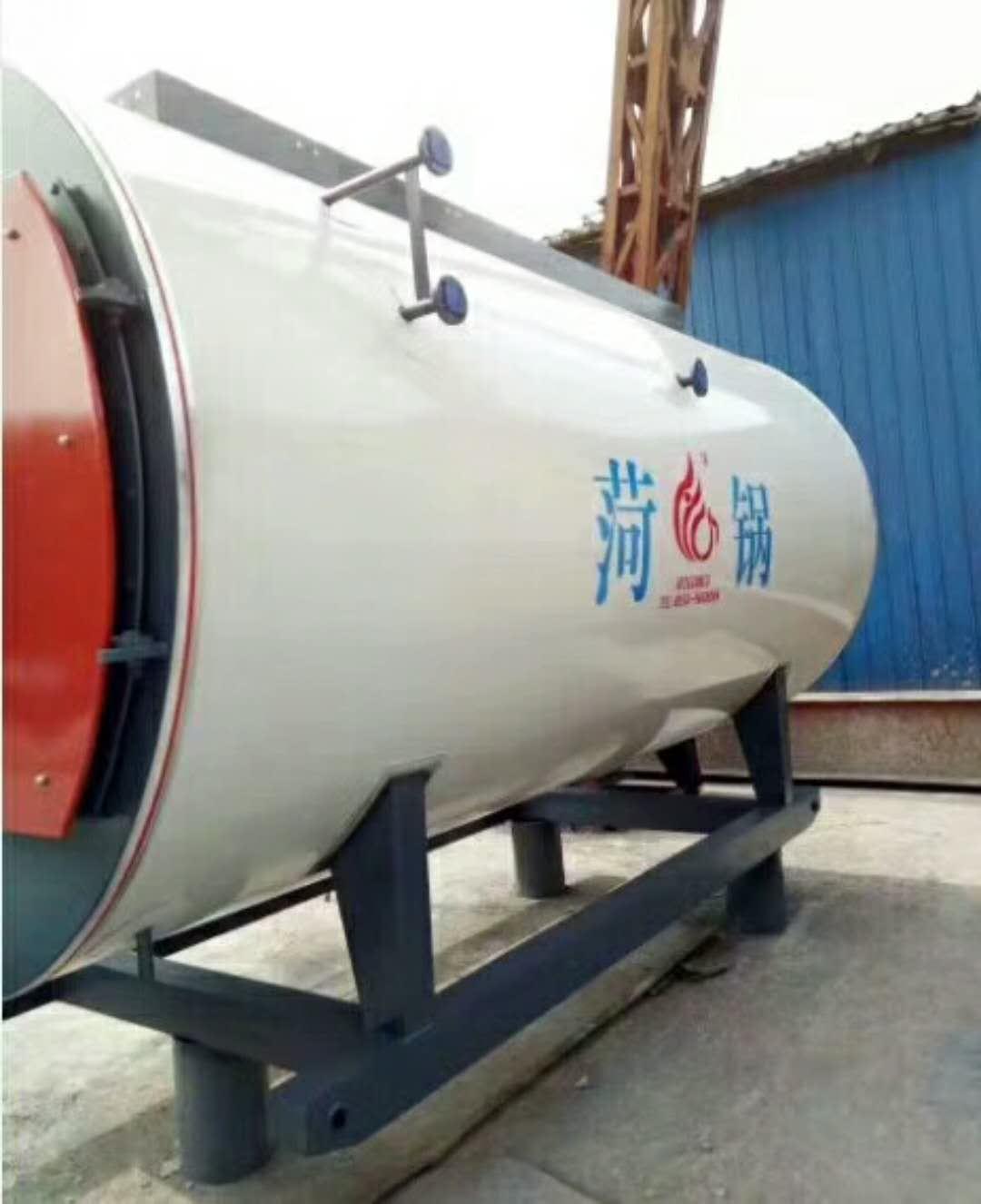
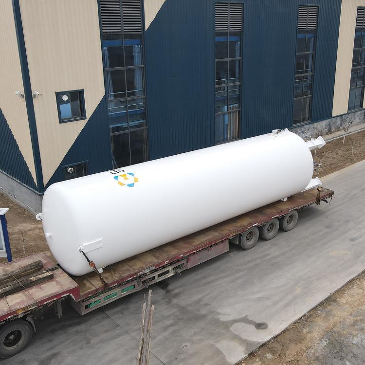
The low-temperature liquid carbon dioxide storage tank is a double-walled container consisting of an inner and an outer vessel. It features vacuum powder insulation and is available in both vertical and horizontal types. The inner vessel is made of 16MnDR material, while the outer vessel material can be selected as Q235-B or 16MnR based on the user's location. The space between the inner and outer vessels is filled with insulating pearl sand and then evacuated. (Available in vertical and horizontal configurations)
2 Uses
Storage: Liquid Carbon Dioxide (LCO2)
3 Insulation Performance
Insulation materials are filled with pearlescent sand under heat and then vacuumed. The standard vacuum level after the sandwich is sealed is:
Effective Volume: ≤ 10m³ with vacuum ≤ 2Pa, 10m³ to ≤ 50m³ with vacuum ≤ 3Pa, > 50m³ to ≤ 100m³ with vacuum ≤ 5Pa. Crafted with precision, unique filling techniques, and a commitment to quality, ensuring optimal insulation performance.
4 Security Technical Features
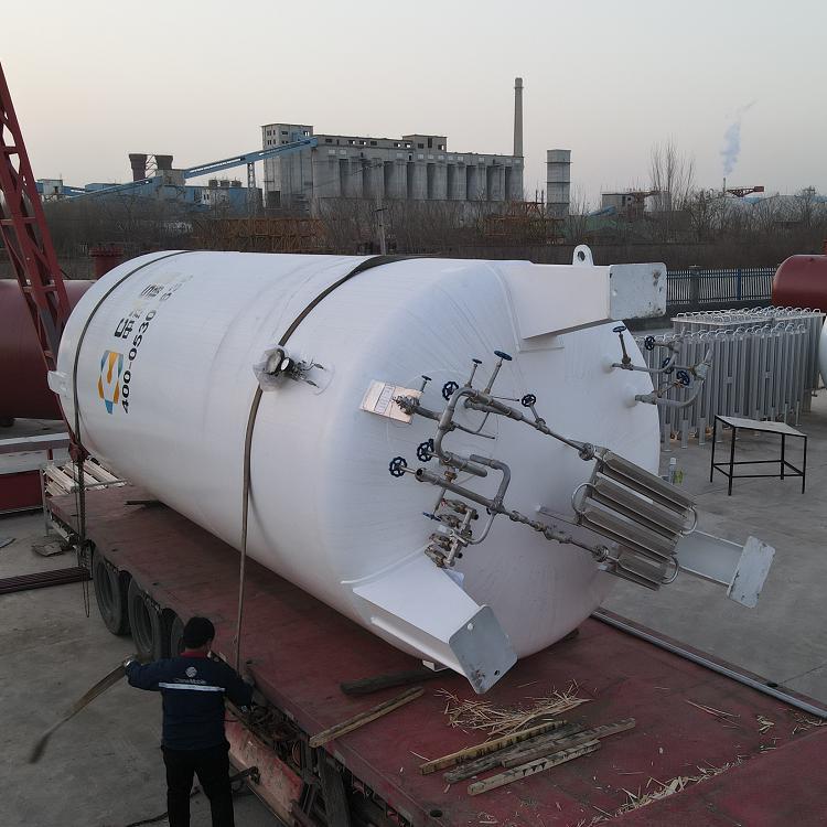
The low-temperature liquid carbon dioxide storage tank utilizes a "combined, safety system valve" that employs two safety valves working simultaneously. During regular safety valve inspections, one side can be shut off while the other continues to operate, ensuring the safe operation of the tank.
OS 5
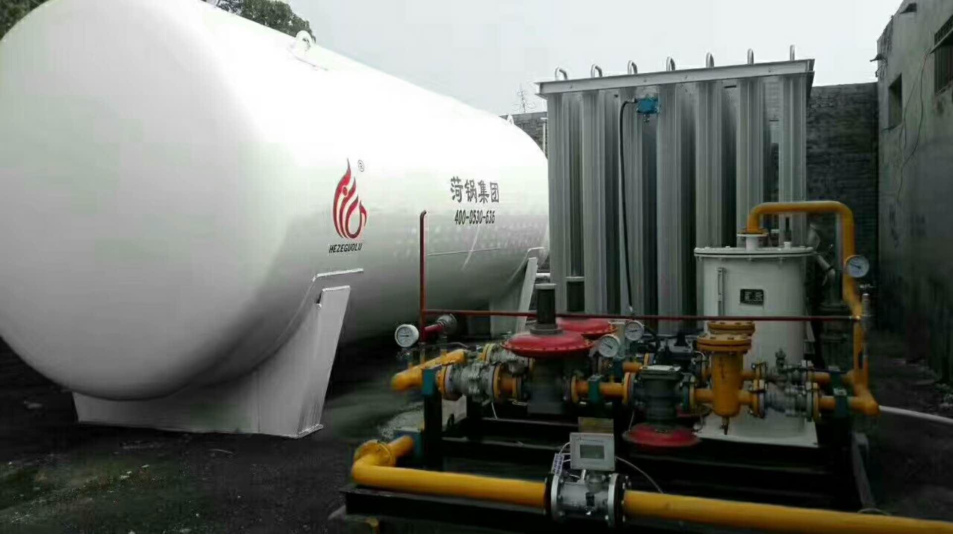
The tank container is equipped with a pressure gauge, differential pressure level gauge, and level reference chart at the top, allowing for real-time monitoring of the storage volume and pressure changes. This facilitates operations during filling and draining.
6 Inspection System
The tank's lower section is equipped with a dedicated tank vacuum detection system, vacuum regulators, and vacuum valves. These can be periodically or on-demand checked with a vacuum gauge to ensure the interlayer vacuum level, thereby guaranteeing the safe operation of the tank.
7 Technical Parameters
Design Pressure: 2.3 Mpa
Working Pressure: 2.16 MPa
Design Temperature: -40°C
Operating Temperature: -20℃
Effective Vessel Capacities: 5m3, 10m3, 15m3, 20m3, 30m3, 50m3
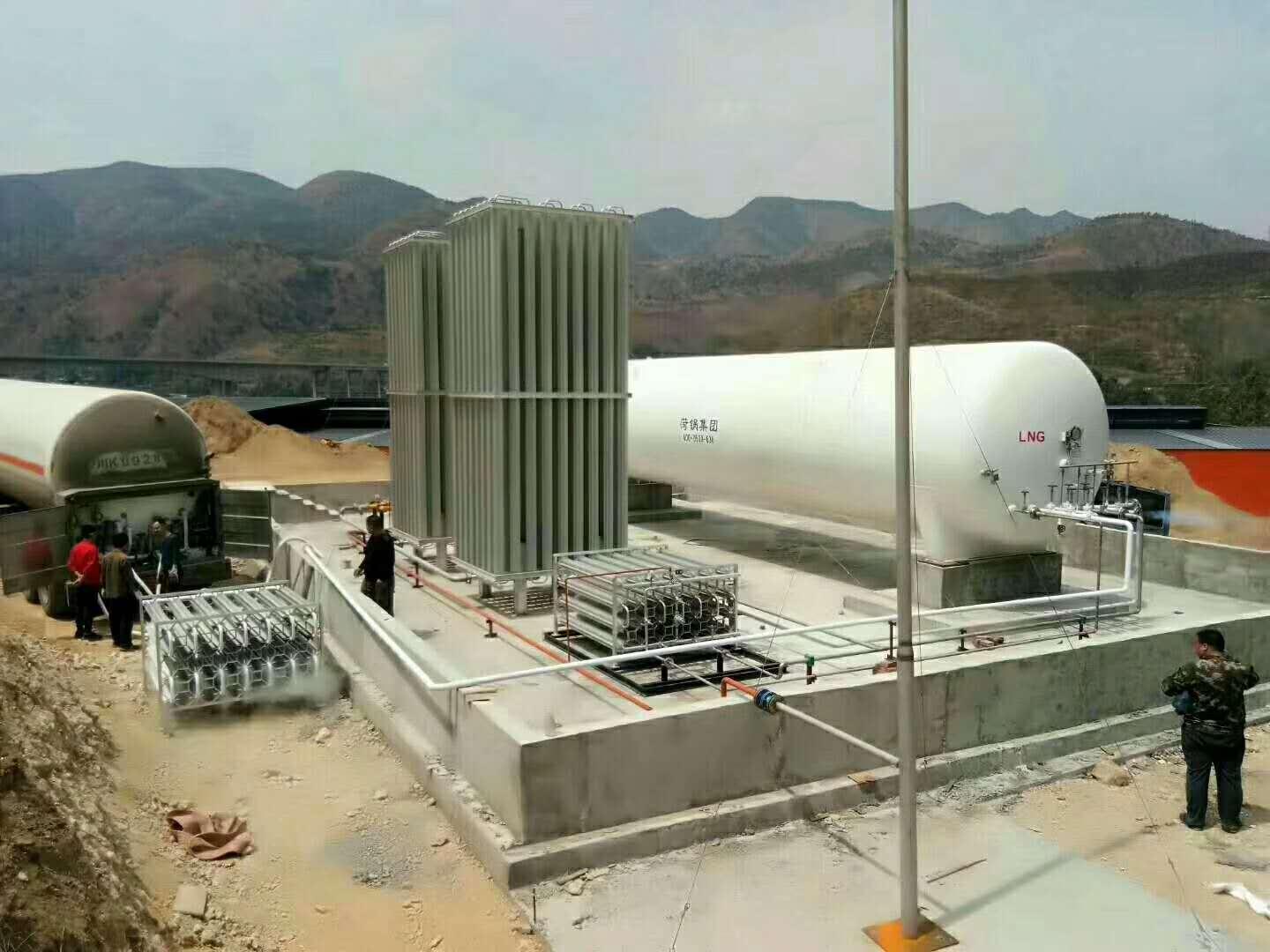
Liquid Oxygen Tank
Overview
This series of low-temperature storage tanks is a double-layer fixed vacuum powder insulation tank (storage tank). The inner shell is made of stainless steel (16MnDR for CO2 storage tanks), and the outer shell is made of Q235B or 16MnR. The surface anti-corrosion coating is achieved through processes such as sandblasting, sweeping, and spraying, along with the use of a two-component rapid curing liquid paint.
Application Scope and Features
Primarily used for low-temperature storage of liquefied oxygen, nitrogen, argon, and carbon dioxide, etc. One cubic meter of liquid can replace 130 gas cylinders. It can eliminate the daily round-trip transportation of gas cylinders, saving a significant amount of human and material resources. Widely applied in industries with high gas consumption such as the gas industry, hospitals, and metal smelting, it is the best product for centralized gas supply. It features a long service life, compact structure, minimal land occupation, centralized control, and easy operation.
2 Product Model
5 cu ft, 10 cu ft, 15 cu ft, 20 cu ft, 30 cu ft, 50 cu ft, 100 cu ft
Technical Data
Maximum Working Pressure: 1.6 MPa
Maximum working pressure of carbon dioxide tank:


Operation Instructions
Utilize security management
(1) The user unit shall apply for and obtain the "Special Equipment Operation Registration Certificate" from the department responsible for special equipment operation registration at the location within 30 days before or after the product is put into use, in accordance with regulations.
(2) Users must comply with the requirements of the "Special Equipment Operation and Management Regulations" for safety management of this product. They should appoint a safety management supervisor, safety staff, and operational personnel, establish various safety management systems, formulate operational procedures, and conduct inspections.
2. Pre-Use Preparation
Tanks and associated piping are installed and placed in position. After passing the acceptance inspection, prepare for pre-use.
Tanks must be purged with dry nitrogen and pre-cooled with liquid nitrogen prior to first use. The purge pressure should not be less than 0.2 MPa.
Prior to blowing, loosen the connections at both ends of the differential pressure (level) gauge, and fully open the combination valve A9 of the differential pressure (level) gauge. Check if there is any water in the exhaust gas flow. If water is present, continue blowing until water stops. Tighten the connections at both ends of the differential pressure (level) gauge, and close the balancing valve to put the differential pressure (level) gauge into normal operating condition.
Before the tank is first filled with LNG, the liquid nitrogen or nitrogen inside the tank should be displaced with LNG gas. First, open drain valve A-6 to vent the nitrogen, then close the drain valve. Open vent valve A-12 and transfer LNG gas from the LNG tank container into the tank via the unloading platform. When the tank pressure reaches 0.1-0.2 MPa, close vent valve A-12, stabilize for 3 minutes, and then open drain valve A-6 to vent. Repeat this process 2-3 times, and the displacement is complete. Use a flammable gas detector or take a sample of the vented air for ignition testing to check the displacement level.
During the initial filling of LNG, the tank should be pre-cooled or checked for previous pre-cooling conditions. The liquid filling rate must be strictly controlled and operated slowly. First, slowly open the upper filling valve A-2, and transfer LNG from the tank car to the tank via the unloading platform. Due to the lag in vaporization when LNG is transferred to the tank, closely monitor the rate of pressure increase inside the tank. The liquid filling amount must be minimal. When the pressure reaches 0.3 MPa, open the gas exhaust valve A-12 to reduce pressure, and close the upper filling valve A-2 if necessary. Through continuous filling and exhaust, pre-cool the tank. After a period of controlled liquid filling, when the tank pressure stabilizes and the liquid level gauge indicates a certain level, gradually increase the opening of the upper filling valve A-2 and open the lower filling valve A-1.
3. Initial Filling Operation for Storage Tanks
(1) Open the upper and lower liquid inlet valves A-2 and A-1, filling both upper and lower sections simultaneously. During the filling process, monitor the differential pressure (level) gauge readings. Open the full indicator valve A-4 to vent the gas in the storage tank. Close valve A-4 immediately upon the release of LNG gas.
(2) When the tank is filled to over 50% of its capacity, valve A-1 should be closed.
(3) Upon reaching 85% capacity of the storage tank, close valve A-2 to stop filling, wait for 5 minutes to stabilize the liquid level in the container, then reopen valve A-2 to continue filling. Open the full indicator valve A-4, and keep filling until liquid starts to flow from valve A-4. Immediately close valve A-4 and stop filling when this occurs.
4. Tank Refueling Operation Procedure
(1) After the initial formal filling, the gas phase pressure inside the tank should be as low as possible during subsequent refilling.
(2) Fill both the upper and lower sections simultaneously. When the differential pressure (level) gauge indicates approximately 50% of the tank's volume, close the lower inlet valve A-1. When filled to about 85% of the tank's volume, close the upper inlet valve A-2, stop filling for 5 minutes to allow the liquid level in the container to stabilize, then reopen the upper inlet valve A-2 to continue filling and open the full indicator valve A-4. Continue filling until liquid starts to drain from the full indicator valve A-4, then close the full indicator valve and simultaneously close the upper inlet valve A-2, and stop filling.
(3) Monitor the pressure gauge and differential pressure (level) meter during filling. (If the pressure rises above the filling transfer pressure or near the safety valve pressure, the exhaust valve A-12 must be opened to release an appropriate amount of gas from the storage tank to relieve pressure.)
(4) Fill out the operation record form.
5. Storage Tank Pressure Boosting Operation Procedure (Valves and equipment for this stage are to be provided and installed by the owner)
Using a supercharger can increase the pressure inside the tank. The boost pressure is controlled according to the discharge requirements and must not exceed the tank's maximum working pressure. The boost system of this tank is controlled by a pressure regulating valve, with the product pressure adjustment range being 0.2 to 0.8 MPa. The boost operation procedure is as follows:
Check if the pressure gauge is in working condition.
(2) Confirm that the boost system pressure regulator valve is open.
(3) Gradually open the bypass valve.
(4) When stopping the drainage, close the shutoff valve to prevent the tank pressure from rising.
(5) Cautionary Notes:
1) During operation, the LNG tank must maintain a liquid level of ≥15%.
2) When operating the boost system, safety must be a priority, with strict monitoring and personnel strictly prohibited from leaving the site without authorization.
6. Tank Pressure Reduction Procedure
Open valve A-12 to reduce the vapor pressure inside the storage tank to no more than the new set pressure of the pressure regulating valve, then close valve A-12.
7. Tank Discharge Procedure
Check that the tank's pressure gauge, differential pressure (level) meter, flammable gas detector, and safety valve are all functioning normally.
(2) Inspect pipeline valves, pressure gauges, and safety valves to ensure they are in normal working condition.
(3) Prepare all explosion-proof tools and wear protective gear.
(4) Inspect the IV line and open drain valve A-6.