


Low Temperature Valve Fault Handling
Common issues with low-temperature valves: stuffing box leakage at the handwheel; leakage at the valve cover nut; internal leakage of the valve; leakage at the valve-pipe connection.
Filler housing leakage at the handwheel and nut leakage at the valve cover, simply tighten with a wrench when the storage tank is not pressurized; absolutely no tightening under pressure is allowed.
Valve internal leakage is usually caused by solid particles in the valve stem or wear from frequent opening and closing. Both the inlet and outlet valves are double-valve designs, with one in reserve. When internal leakage is detected, shut off the reserve valve and repair the leaking valve. First, loosen the valve cover nut with a wrench, remove the valve stem, and dry the valve disc and cover stem with a hairdryer; then clean the valve body sealing surface and the valve disc sealing gasket, wiping away any frost or water. If the valve disc gasket shows unevenness, cracks, or grooves, replace it immediately with a spare. If the valve body sealing surface shows wear marks, smooth it with metallographic sandpaper (if not available, use the back of fine wood sandpaper). Before reassembling, thoroughly clean any dust and frost or water, and tighten the valve cover nut.
When leakage is found at the valve-pipe connection, please have a qualified unit perform the repair. During the repair, drain the liquid completely and empty it. For oxygen equipment, the oxygen content should be replaced to less than 21%. Before welding, position the valve halfway open and loosen the valve cover nut. After welding, retighten the nuts and conduct an airtightness test on the piping.
Differential Pressure (Level) Gauge Fault Handling
Common issues include malfunctioning indicators and pointer trembling.
1) A malfunctioning indicator can be a pointer that fails to return to zero or remains fixed at a certain value. If it's the former, it's usually due to improper use, such as the combination valve of the differential pressure (level) gauge not being in a balanced state before filling, preventing the pointer from returning to zero. Open the combination valve after liquid enters through the lower inlet. If the deviation from zero is minimal, you can loosen the screw securing the gauge pointer, adjust the pointer to zero, and then tighten the screw again.
2) Pointer tremors are usually due to instrument tube leaks; carefully inspect the instrument tube, the combination valve of the level gauge, and the relevant joints of the pressure gauge. Additionally, if overfilling the liquid causes differential pressure (level) gauge tube to take in liquid, it may also exhibit tremor.
(4) Summary of Fault Handling Methods
Potential Faults During Use, Causes, and Solutions Are Shown in the Following Table
Troubleshooting Methods
Fault Phenomenon Cause Solution Method
During use, internal pressure
An abnormal increase has occurred: a. The turbocharger's intake valve is not sealed properly, causing internal leakage. The turbocharger's intake valve is undergoing grinding and inspection.
b. The pressure gauge reads inaccurately. Repair or replace the pressure gauge.
Pressure (Level) Gauge Indication is Inaccurate a. Pressure (Level) Gauge Failure. Inspect the Pressure (Level) Gauge.
b. Leaks in the upper and lower pipes of the differential pressure (level) gauge. Repair and seal.
c. Leaking at the differential pressure (level) gauge connection. Repair and remove the leak.
Evaporation rate exceeds design
Value, top sweating and frosting a. Inadequate closure of the vapor vent valve, internal leakage. Valve grinding and maintenance required.
b. Vacuum degradation. Re-evacuate the vacuum.
c. Top pearl sand has settled, pearl sand not fully packed. Refill pearl sand, re-evacuate vacuum.
Leakage of liquid or gas from the valve cap or joint. a. The sealing gland is not tightened properly. Tighten the gland cover.
b. Seal ring damaged. Replace the seal ring.
c. Seal face damage. Repair or replace parts.
d. Weld Seam Leak - Patch welding (but should be performed according to patch welding requirements).
Heze Boiler FactoryLimited Company
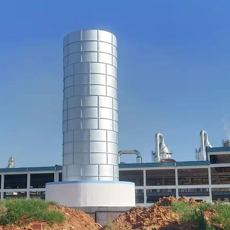
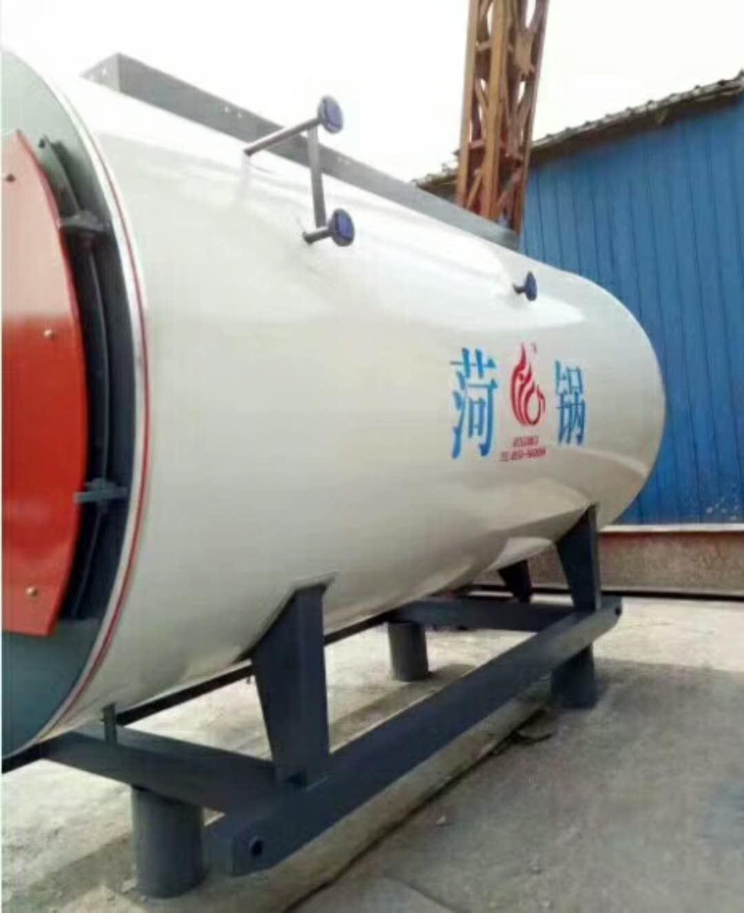
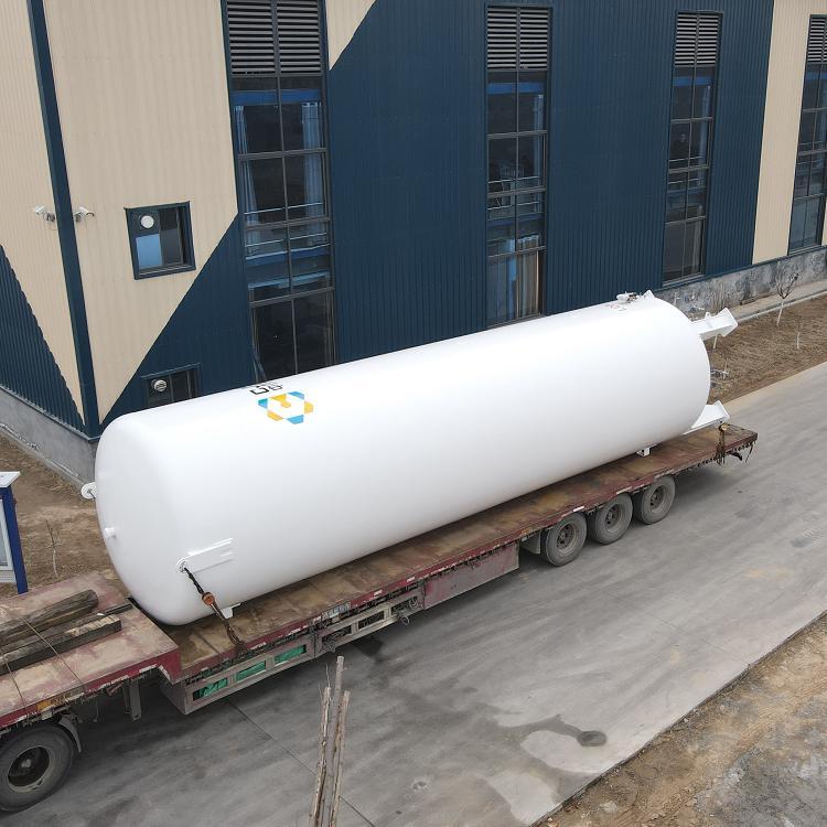
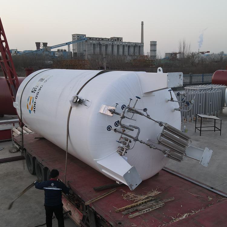
LNG Storage Tank
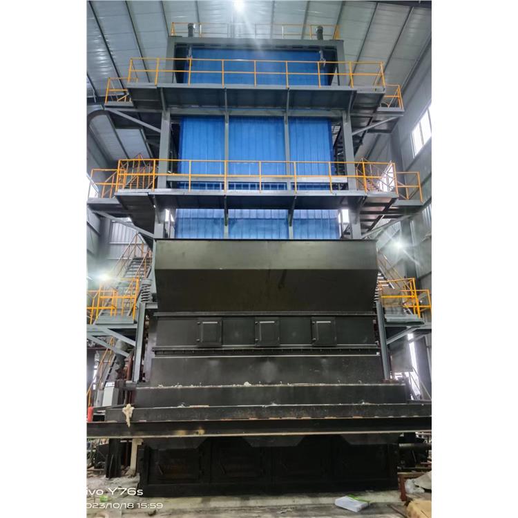
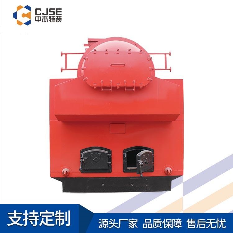
Heze Boiler FactoryOur Company specializes in manufacturing various models ofGas boilers, biomass boilers.LNG tanks, LPG tanks, featuringBGrade A boiler manufacturing qualificationA2Grade pressure vessel design and manufacturing qualifications2Grade boiler installation andGB、GCClassified pressure pipeline installation qualifications, equipment and machinery installation qualifications, etc.Annual production capacity exceeds 1,000 units, with some products available in stock. Please call for inquiries.
LNG liquefied natural gas storage tanks are specialized products for storing liquefied natural gas, a special type of equipment, classified as a third category pressure vessel. They are made of 06Ni9DR material and undergo non-destructive testing, hydrostatic and pneumatic tests, on-site inspection by the Technical Supervision Bureau, and are issued with pressure vessel inspection certificates. The manufacturing process includes external rust removal and painting, etc. The liquefied gas storage tanks undergo strict quality assessment for the material of the pressure components, appearance dimensions, weld quality, operational quality, installation quality, internal equipment, and safety accessories.
Routine physical and chemical tests for the material of the container, such as mechanical properties and chemical composition.
The weld joints, seams, tank end caps, and mutual geometric positions of all pressure elements are rigorously inspected via X-ray non-destructive testing and magnetic particle inspection. Tests are conducted on the product's sealing, pressure resistance, and any technical indicators that could affect the safe operation of the product.
LNG Storage Tank


专用LNG储罐-哪里有LNG储罐批发-供应LNG储罐厂家直销-哪家LNG储罐加工