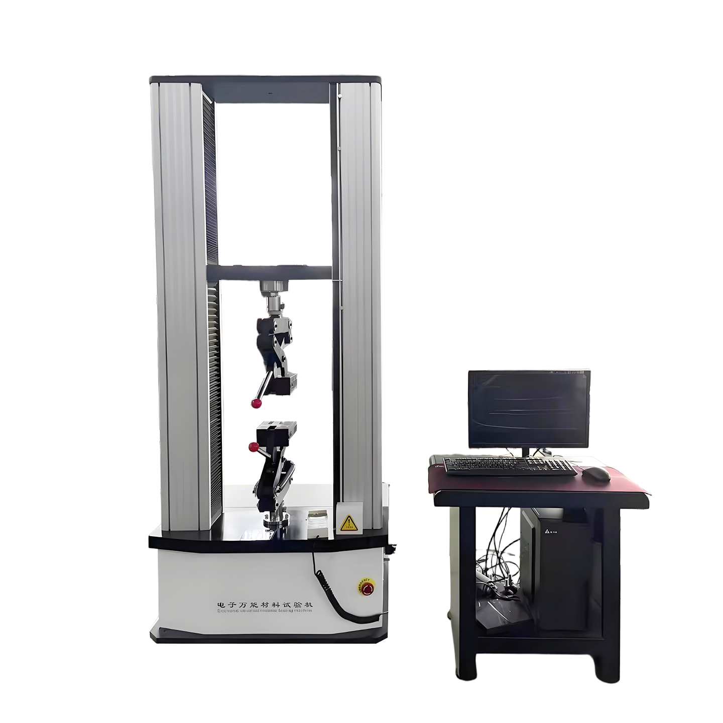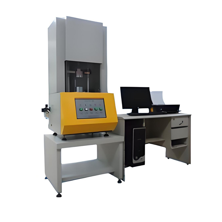


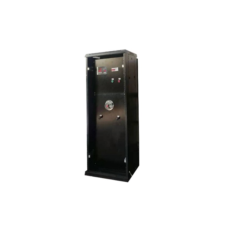


JZL-D TypeRubber Tensile TesterSuitable for determining the tensile, tear, and peel mechanical properties of materials; when using a reverser, compression tests on the material can be conducted.
This machine is a new type of economic material testing machine with variable speed control, equipped with a force sensor and an automatic elongation tracking device. During the testing process, the microcomputer continuously collects signals from the force sensor and the automatic elongation tracking device, and performs formatted data processing according to the test requirements. Its features include simplicity of use, stable performance, advanced technology, high level of automation, and high testing accuracy.
One,Rubber Tensile TesterKey Technical Specifications
1.1 Range: 10N, 20N, 30N, 50N, 100N, 200N, 300N, 500N, 1KN, 2KN, 3KN, 5KN. The machine's range does not exceed 5000N.
1.2 Force Precision: ±0.5% of indication.
1.3 Test Speed: 10mm/min to 500mm/min
1.4 Effective Stretching Distance: 900mm. (Excluding Fixture) (Standard Specifications)
1.5 Position Measurement Accuracy: ±0.5% of reading.
1.6 Power Supply: AC 220V ±5%, 50Hz
Machine Size: Approximately 640×720×2000 mm (L×W×H).
Machine Weight: Approximately 280 kg.
Section II: Environmental and Operating Conditions for Rubber Tensile Testing Machine
2.1 Temperature range: 0~40℃
2.2 Relative humidity below 80%;
2.3 Has an independent grounding wire.
2.4 In a non-impact, non-vibration environment;
2.5 In environments with no significant electromagnetic field;
2.6 There should be at least 0.7m of space around the testing machine, and its working environment should be clean and dust-free.
2.7 Base and frame levelness not exceeding 0.2/1000.
Section 3:Rubber Tensile TesterSystem Composition and Working Principle, Testable Items
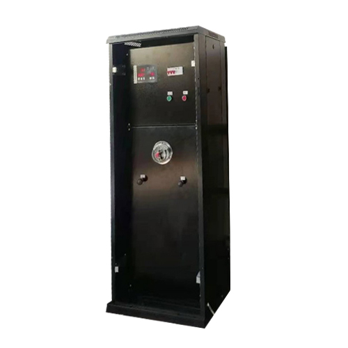
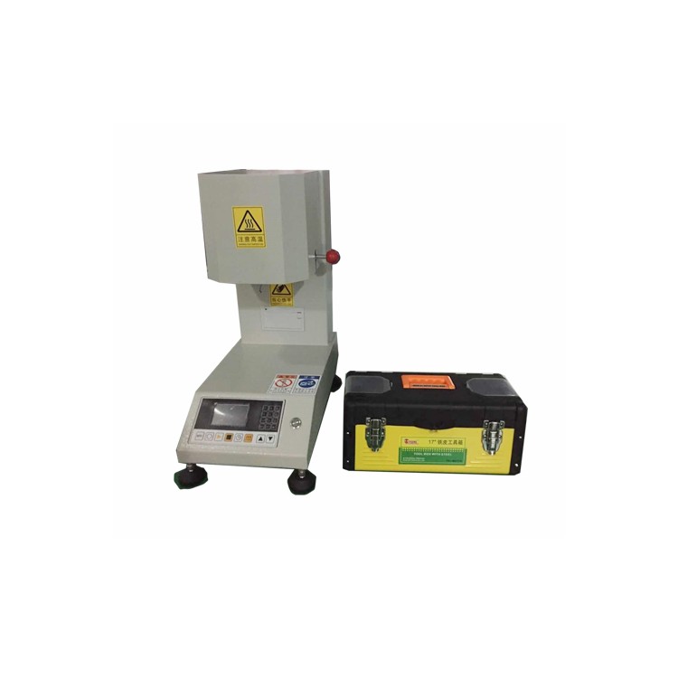
3.1 The system consists of three parts: the main unit, electrical control system, and digital control system.
3.2 Working Principle
3.2.1 Principle of Mechanical Transmission
3.4 Standard Test Items: (Standard Display Values and Calculated Values)
● Tensile Stress ● Tensile Strength
● Tensile Strength ● Tensile Elongation
● Tensile Stress
● Tensile Strain Rate
● Tensile Stress Value ● Tearing Strength
● Any point force value ● Any point elongation rate
● Extraction Force ● Adhesion and Peak Value Calculation
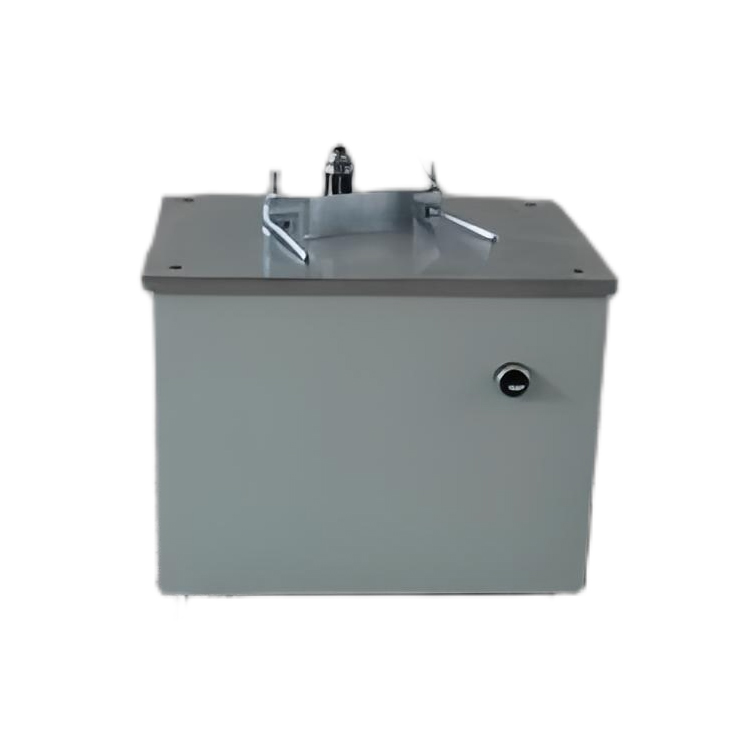
The Jiangdu Jinguo Tensile Machine mainframe is composed of an electric motor and controller, ball screw, guide column, moving crossbeam, limit device, etc. The sequence of mechanical transmission is as follows:
Motor - synchronous belt pulley - screw - test bench
4.2.2 Force Measurement System: A tensile sensor is installed on the moving beam of the main unit, with its lower end connected to the upper clamp. During the test, the force applied to the specimen is converted into an electrical signal by the force sensor and input into the microcomputer acquisition and control system.
4.2.3 Automatic Extension Tracking Device: This device is used to measure sample deformation, consisting of two low-resistance tracking clamps that hold the sample. As the sample is subjected to tensile force and deforms, the distance between the two tracking clamps also increases accordingly. The tracking clamps convert the linear motion into rotational motion through a rope and pulley, and the displacement is then converted into an electrical signal inputted into the microcomputer acquisition and control system by a tracking encoder.
4.3 Limiting Protection Device and Clamping Jig
4.3.1 Limiting Protection Device
The limiting protection device is a crucial component of the machine. The main unit is fitted with a limiting rod, which is equipped with two adjustable rings that can move up and down. During the testing process, when the stopper comes into contact with the ring, it will drive the limiting rod to move, enabling the limiting device
Cut off the passage in this direction, the main engine will stop running. At this point, running in the opposite direction will allow the test machine to operate normally. Adjusting the position of the stopper on the limit rod can limit the travel of the moving beam, providing great convenience and a safe and reliable protection for conducting tests.
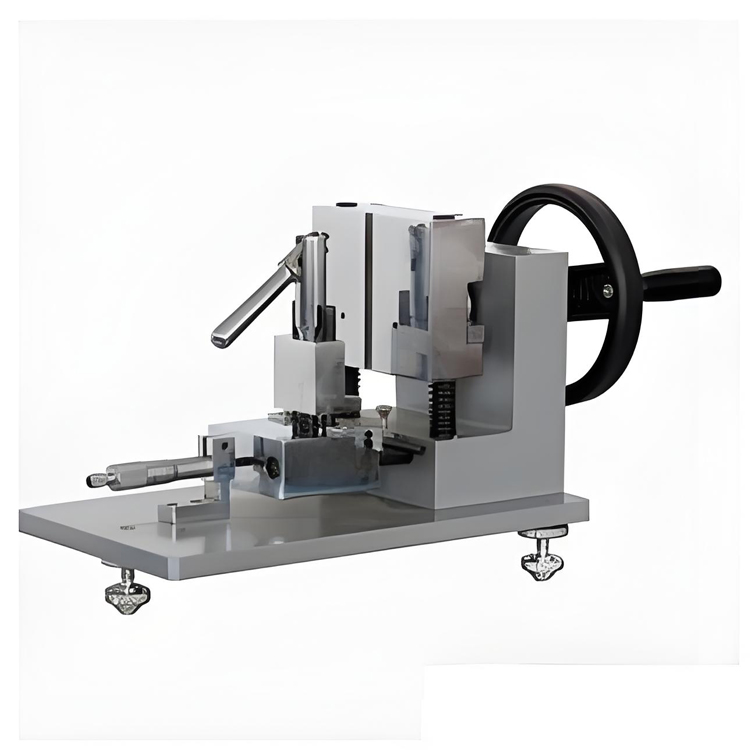
4.3.2 Fixture
Our company offers a variety of general and specific holding fixtures for sample clamping, including wedge-type jaw fixtures, wrapping metal wire fixtures, film stretching fixtures, and paper stretching fixtures, etc. These are capable of meeting the clamping requirements for performance tests on various materials such as metal and non-metal sheets, strips, foils, bars, wires, fibers, plates, rods, blocks, ropes, fabrics, and nets, and can be customized according to customer specifications.
5. Installation and Debugging
5.1 Mechanical Installation
Position the main unit vertically at the point of use, adjust the lower foot screws of the main unit, and check the workbench level with a level (longitudinal and lateral levelness 0.2/1000).
5.2 Electrical Installation
5.2.1 Plug the force sensor connector into the force sensor interface and the displacement sensor connector into the displacement sensor interface.
5.2.2 Upon completion of the aforementioned work, the system can be powered on. There is a boat-shaped switch on the back panel of the microcomputer collection system. Place the switch in the 'on' position to activate the power supply.
5.2.3 Power on the main unit, turn to engage the pop-up power switch.
5.2.4 The microcomputer system must be preheated for 20 minutes after startup before it can operate normally.
6. Instrument Usage and Operation
6.1 First, check and confirm that the main machine of the testing machine and the microcomputer control system's cable connections are properly and correctly made.
6.2 To stop or shut down the machine immediately during the rotation pop-up test machine operation, press the "Emergency Stop" button. Power on the microcomputer control system.
7. Attachment
7.1 One-year warranty certificate for the tensile testing machine and a Chinese operating manual each.
7.2 Free gift set of standard tensile testing machine fixtures (other fixtures available for purchase).
7.3 One set of tensile testing machine test software.
A set of brand-name computers and one color printer
8. Cautionary Notes
8.1 Before powering on, check the connections between the CNC system and the main unit, including cables, plugs, sockets, and power plug sockets, to ensure they are properly connected and not loose. Confirm that everything is correct before powering on (e.g., a loose ground wire under the power socket in the CNC system controller can cause the main unit to lose control). Always remember the power-on sequence: first, turn on the power of the test machine's main unit, then the CNC system power. When shutting down, turn off the power of the test machine's main unit first, then the CNC system power. Do not remove any plug after powering on.
8.2 It is crucial to check the position of the upper and lower limit position bushes, ensuring a certain distance between the two clamps to prevent damage to the machinery due to misoperation or loss of control of the main unit, especially the sensors.
During the test process, please do not press any keys on the microcomputer control system.
8.4 Select the fixture based on the specific test conditions to avoid damaging the fixture.
8.5 Sudden power outage: immediately shut down all power sources and restart in order after confirming stable power supply. Frequent and multiple interruptions in power supply can easily damage the microcomputer control system and the motor speed control system.
8.6 Do not stand too far from the machine while the main unit is in operation.
8.7 The input tensile speed value must match the actual tensile speed of the testing machine, especially during tearing and peeling tests.
8.8 Do not perform tensile tests when the breaking force value of the unclear sample is not specified, as it may damage the sensor due to overload.
Nine.Rubber Tensile TesterSoftware Test Instructions
9.1 The test software under Windows XP operating system can achieve control modes such as fixed load, fixed displacement, and fixed time to meet different testing requirements.
9.2 The test software supports random switching among languages such as Simplified Chinese, Traditional Chinese, and English.
9.3 Units such as force and displacement can be freely switched.
9.4 During the testing process, curves for load-time, load-displacement, displacement-time, stress-strain, and load-two-point elongation can be switched on demand.
9.5 During the testing process, the current values of the applied load and displacement are displayed. The tensile strength, compressive strength, elongation, tear strength, peel strength, and bonding strength of the material can be automatically calculated when the input area and gauge length data are entered.
9.6 Multiple material tests can be conducted for curve overlap comparison, with the display of test result values, minimum values, and average values.
9.7 Test results can be automatically saved or manually saved.
After the 9.8 test, you can print batch sample and individual sample data and graphic reports.
9.9 Software conveniently allows customers to reserve the option to add special feature modules.
9. Enjoy lifetime service and free upgrades.
10. Equipment Maintenance and Repair
10.1 Apply lubricating oil to sliding parts, and rust-prone parts with anti-rust oil. Clean and oil the lead screw and guide column once every three months. When refueling, loosen the foldable cloth on the top of the moving beam and use grease or hyperbolic gear oil.
10.2 Prevent the intrusion of high temperatures, excessive humidity, dust, corrosive media, water, etc., into the instruments.
10.3 Keep clean and prevent rusting.
10.4 Conduct regular inspections to maintain the integrity of its components.
10.5 An annual periodic calibration is required.
10.6 Record usage.