


Working Principle and Key Features
2. 1 Operation Principle
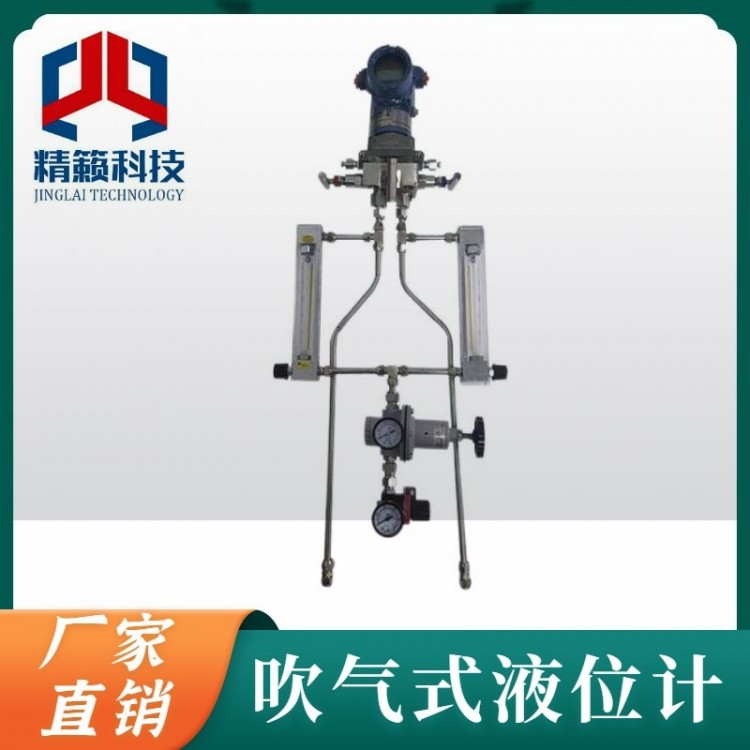
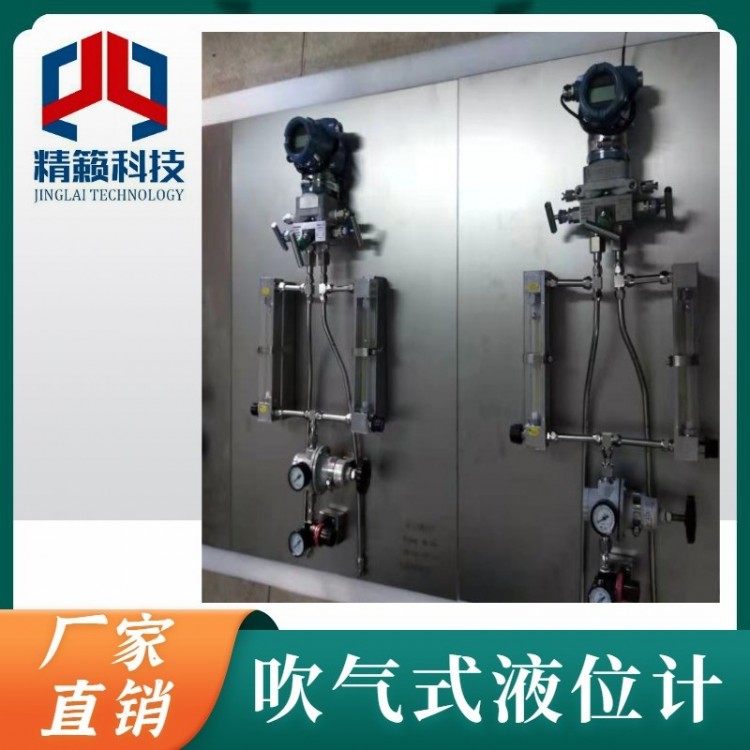
The blow-off level gauge is mainly composed of three parts: the blowing device, a differential pressure (pressure) transmitter, and the blowing pipe circuit. Single-channel blowing devices are suitable for measuring the level of atmospheric or open containers, while dual-channel blowing devices are used for measuring the level of pressurized containers.
The working principle of the blow molding level gauge is as shown in the figure. 2.1 As shown.

2.1 Working Principle of an Inflated Level Gauge
The gas, after being filtered and depressurized, enters the blowing device and is steadily released as bubbles through the end of the blowing tube inserted into the medium being tested, via the blowing tube circuit. Due to the very small flow rate of the gas being discharged from the blowing tube,A Location Gas Pressure PA Equal to the pressure of the liquid medium.B Gases gases PB Equal to PA Added AB Two-point pressure differenceDPABAir hose D Gaseous Pressure PD Equal to C Gas Pressure PC Added CD Two-point pressure differenceDPCDMeasure through a differential pressure transmitter BD Two-point differential pressureDPBD You will obtain the liquid level height of the container. h。
PA-rgh=PC,
PB=PA+DPAB, it can be concluded that:
PB=PC+DPAB+rgh,
PD=PC+DPCD,
DPBD=rgh+DPAB-DPCD, in the formularFor liquid density,g For local gravitational acceleration.
AB、CD Pressure difference between AB The distance between the two pipeline sections and the flow rate are related. When designing pressure readings, strive to make AB The distance
With CDThe distances are consistent, as are the flows.DPAB=DPCDThus,DPBD=rghBy measuringDPBD The liquid level height within the container can be calculated. h。
The blow-through level gauge can be understood as a non-contact liquid level measurement instrument, capable of measuring liquids in both open and closed containers. Apart from the blowing tube coming into contact with the medium being measured, the blowing device and the pressure differential (pressure) transmitter measuring elements do not come into contact with the medium, thereby protecting the measuring elements, reducing maintenance requirements for the instrument, and enhancing measurement reliability. Since the blowing device ensures a constant flow of gas output, the pressure measured by the pressure differential (pressure) transmitter automatically follows the change in pressure at the blowing tube outlet. Therefore, the signal output by the pressure differential (pressure) transmitter is correspondingly related to the liquid level height.
Bubble-level liquid level gauges are not only suitable for measuring the level of clean liquids but are particularly well-suited for corrosive acid, alkali, and salt liquids, liquids with high viscosity, crystalline liquids, high temperatures, liquids containing solid particles, as well as the level measurement of some fluidized bed materials.
2.2 Key Features
The liquid level measurement system composed of blowing devices has no moving parts, with the exception of the blowing tube, the other measuring elements do not come into contact with the medium being measured.
Single-table installation, panel installation available with single, dual, or multi-way structures.
Compact and sturdy, it integrates the main components required for measurement onto a single panel, facilitating installation and maintenance.
All-mechanical structure with good sealing, low failure rate, and minimal maintenance required.
3 Key Technical Specifications
Measurement Accuracy: ±0.5%F.S.。
Measurement Range:0-250 kPaCorresponding to the water level height is 25 m。
Response Time:0.5 s。
Pipe Length:£ 25 m。
Blower Tube Material:304S.S.、316S.S.、316LS.S.、PVC。
Process connection flange standard:HG/T 20592-2009Dual-path:DN80 PN40Single Route:DN25 PN40。
Structure Types: Single Table Installation, Single-Lane Panel Installation, Double-Lane Panel Installation.
Source Pressure:£ 0.8 MPa。
Power Supply:24V DC。
Signal Output: Two-wire system 4-20 mA DC Or secondary system 4-20 mA DC+HARTâCommunication Protocol.
4 Outline dimension drawing
4.1 Installation Drawing of Single-Table Blowing Device with Dimensions

Image:
1 Filter Pressure Reducing Valve2 Pressure Gauge3 Pressure Regulator4 Flowmeter5 Flow Control Valve。
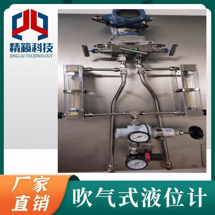
4.2 Panel Mount Single-Blow Device Outline Drawing

Image:1 NPT 1/4 - M20x1.5 Adapter Fitting2 Nuts, 3 PTFE Washers, 4 Welding Short Tubes

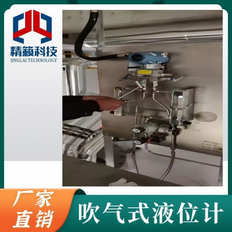
Image:
1 Inlet shut-off valve: Open or close the blow air source.
2 Gas Source Pressure Indicator Gauge: Gas Source Pressure Indicator.
3 Pressure Relief Valve: Increases or decreases blowing pressure.
4 Airflow Adjustment: Adjust the size of the blowing airflow.
5 Blowing Pressure Gauge: Indicates the blowing pressure after the pressure reducing valve.
6 Export shut-off valve: Controls the gas flow to the blow pipe, opening or closing it.