


The hard rod magnetostrictive liquid level gauge is an innovative product with high precision and reliability, effectively addressing the liquid level and interface measurement in extremely harsh operating conditions. Its measurement process is unaffected by changes in temperature, pressure, dielectric constant, and other factors due to the use of magnetostrictive technology. Its high precision, stability, and maintenance-free features effectively eliminate the shortcomings of traditional electric float switches, differential pressure transmitters, radar, and other liquid level products in field applications, thus widely used for high-precision measurements of various liquid levels and interfaces.
Electronic meter head section:
| Measurement Parameters | Level, Interface | Repetitive | ±0.38mm or 0.01% full scale |
| Non-linear | ±0.79mm or 0.02% of full scale | Precision | ±0.38mm or 0.01% of full scale |
| Power Supply | 16~30VDC, Reverse polarity protection | Ambient Temperature | -40~65℃ |
| Display | LCD | Signal Output | Two-wire system, 4-20mA/HART, Modbus or Profibus |
| Loop Resistance | 620Ω(24VDC) | Power Consumption | 0.65W |
| Damping | 0~32S | Ex-proof rating | Ex ia IIC T4,Ex d IIC T6 |
| Resolution | Analog: 0.01 mA; Digital: 0.01 full scale | Fault Signal | 3.86 mA or 20.96 mA |
| Humidity | 0~100 | Table Header Structure | Dual-chamber |
| Outer Shell Material | Die-cast aluminum or stainless steel | Shell Treatment | Polyester Coating (for Die-Cast Aluminum Only) |
| Electrical Interface | 1/2 NPT(F) or M20×1.5 | / | |
Pole Assembly Components:
| Process Pressure | Vacuum ~ 26 MPa | Process Temperature | -196~427℃ |
| Range | 0.15~9.1m | Probe Outer Diameter | 5/8" or 3/4" (high-pressure type) |
| Top Dead Center | N/A | Bottom Dead Center | Less than 2.5" (63mm) |
| Response Time | 0.1 second | Process connection | NPT or flanged connection, welding |
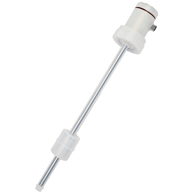
| Probe Rod Material | 316L SS, 316L SS lined with PFA, 317L SS, Hastelloy C-276, Zirconium 702, titanium materials, etc. | / | |
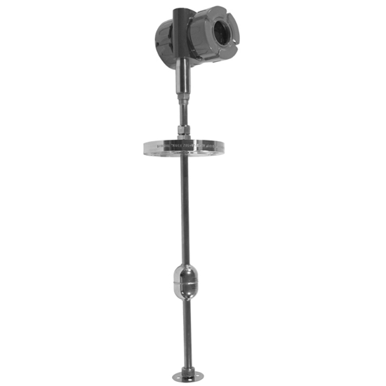
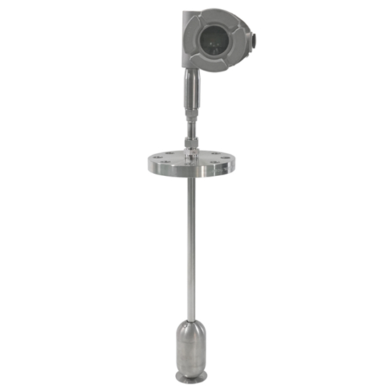
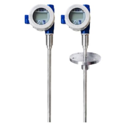
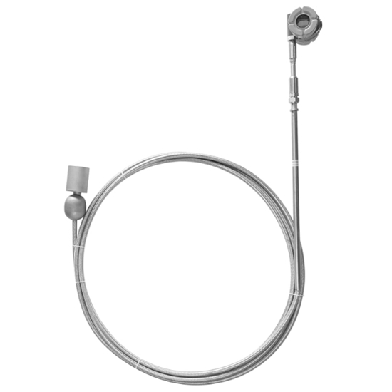
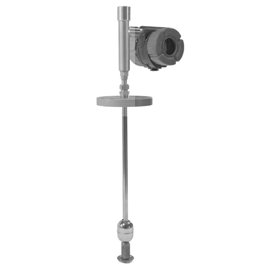
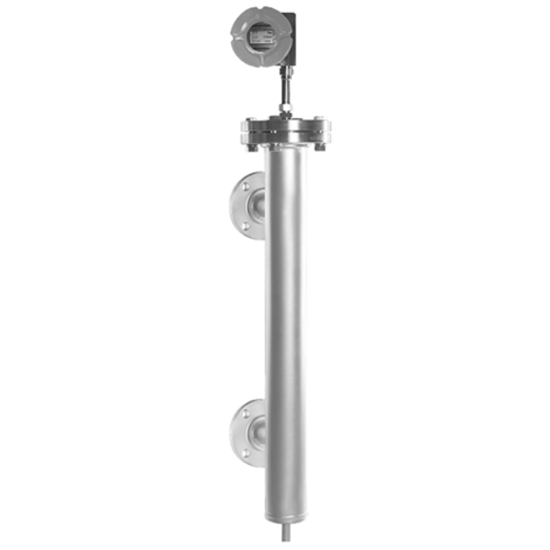
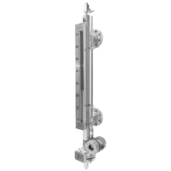
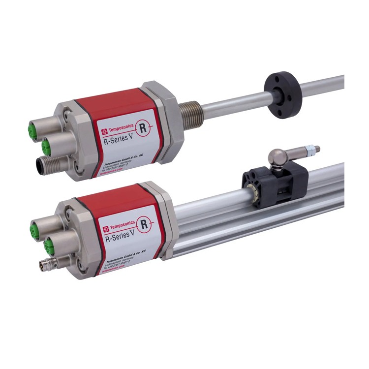
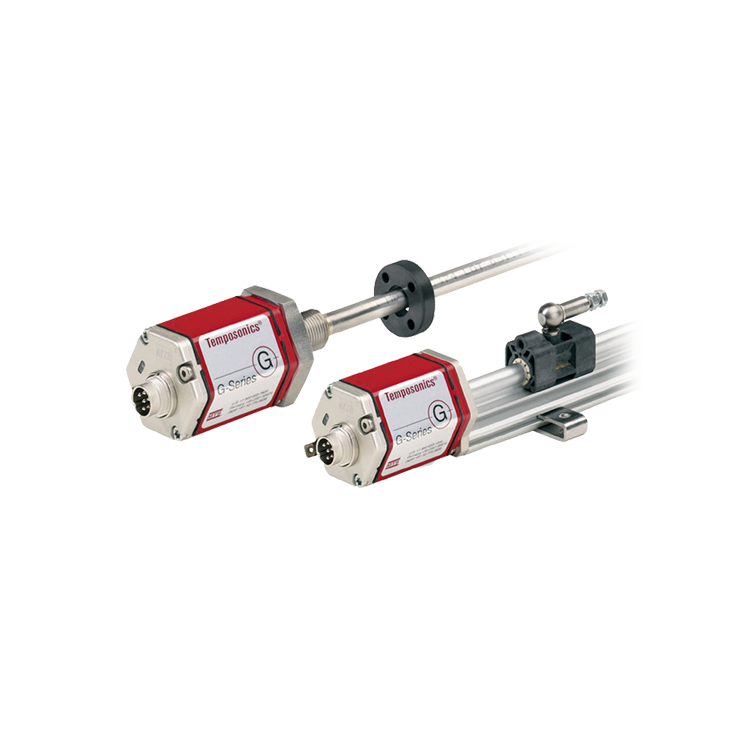
Dimensions and Structure:

Features:
Multi-functional: capable of measuring liquid level and interface individually or simultaneously
High precision: Measurement accuracy up to ±0.38mm or 0.01% of full scale (take the larger value)
Maintenance-free: Core components do not come into direct contact with the medium, requiring no regular maintenance
Non-calibrated: Intelligent design, parameters automatically stored, no physical calibration required
User-friendly: Standard buttons, no additional auxiliary devices required
Easy installation: Simple to install, NPT/Flange connection
High safety: Ex ia IIC T4, Ex d IIC T6 explosion-proof rating and IP68 protection rating
Low power consumption: LCD display, two-wire system powered by 4~20mA/HART, Modbus, or Profibus output options available
Application Industry and Equipment:
Boilers: Steam Drum Level
罐区: Refinery, Oil Storage, Gas Station, Chemical Products Warehouse, Petrochemical Company Storage
Power: auxiliary equipment level (high-pressure, low-pressure, deaerator, condenser, shaft seal heater, etc.), chemical water treatment
Silicon Industry: Organosilicon, Polysilicon
Petroleum & Petrochemical: Oil and gas exploration and collection, refining, ethylene, and polycondensation, etc.
Other: Metallurgy, Papermaking, Water Treatment, Biology, Food & Beverage, Light Industry, etc.
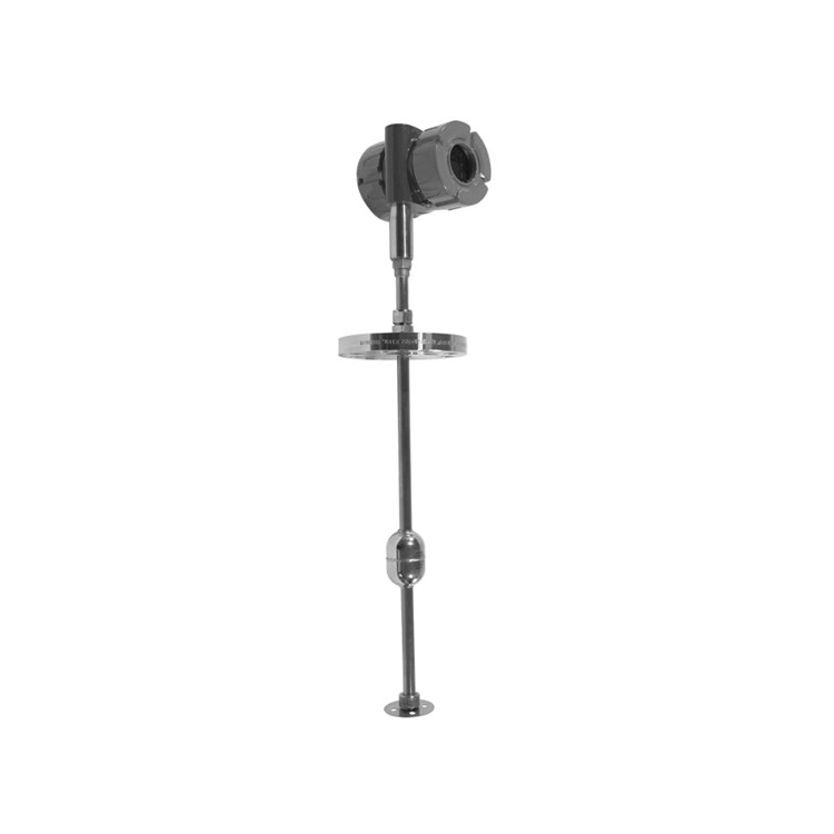
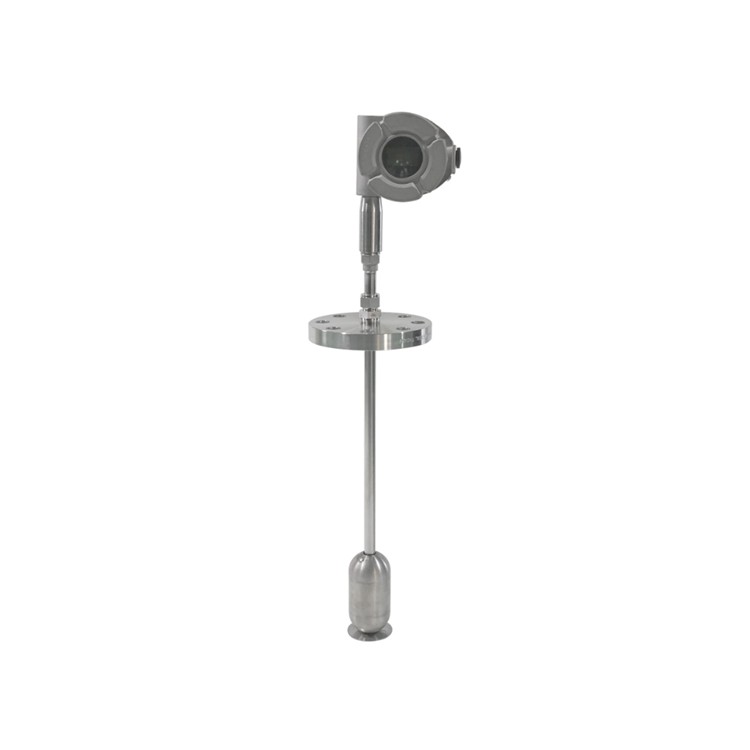
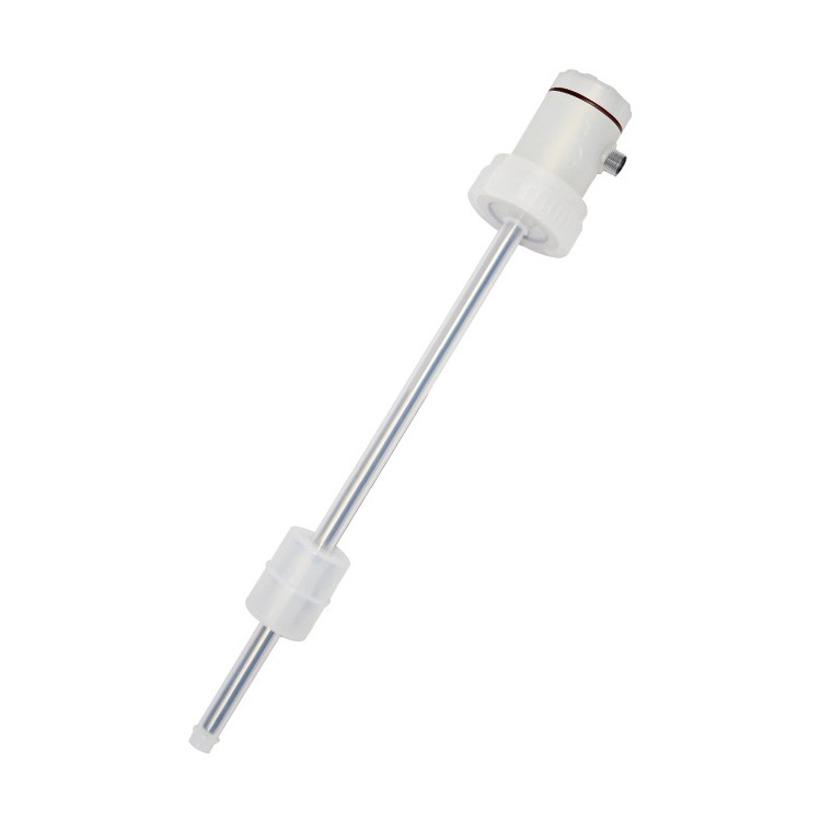
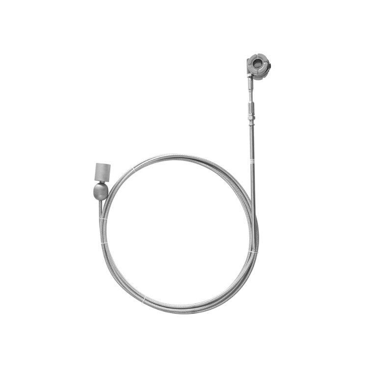
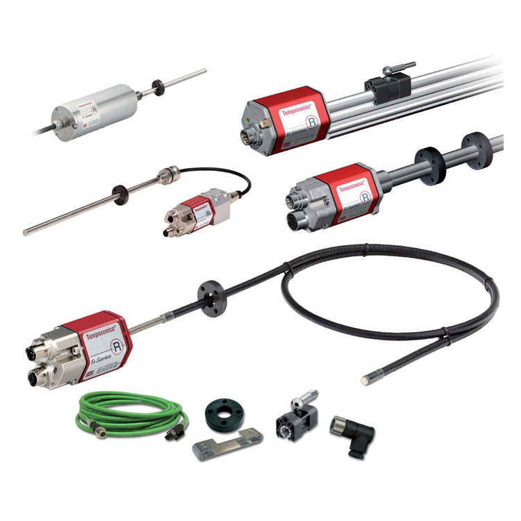
Product Structure:
The magnetic伸缩level gauge features a modular design, with a simple structure consisting of three parts:
Electronic Meters: Housing, Circuit Board, Electronic Module
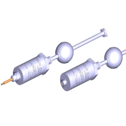
Probe Assembly: Probe, Sensor, Magnetostrictive Wire, Buoy
Accessory Components: Buoyancy Floats and Top Flanges, etc.

Installation:
Avoid bending or damaging the level gauge probe during installation. If the probe bends, it will hinder the float's free movement along the probe, thereby affecting the measurement results. The installation steps are as follows:
1. Ensure the float size can easily fit into the buoy or mounting hole, and that the related accessories are suitable.
2. The float is directly mounted onto the probe rod of the liquid level gauge and can move freely on the rod. When installing the float, ensure that the direction marked with "UP↑" aligns with the measurement direction.
3. Clean the probe rod and float of the level gauge, removing any attachments and stains.
4. Ensure alignment at the "0" point during installation. If the ordered product requires a fixed flange, install it directly at the site. If the ordered product does not specify a fixed flange, align the "0" point during on-site installation; when the level gauge indicates 0mm liquid level, secure the level gauge to the installation flange.
5. When the process temperature exceeds 150°C, a high-temperature bracket must be installed for the top probe of the flange to ensure proper heat dissipation and reinforcement of the gauge.
6. Clean off any deposits or stains that accumulate during the surface installation of the level gauge.