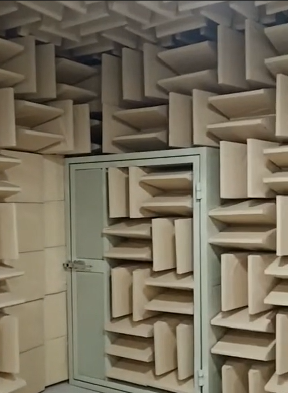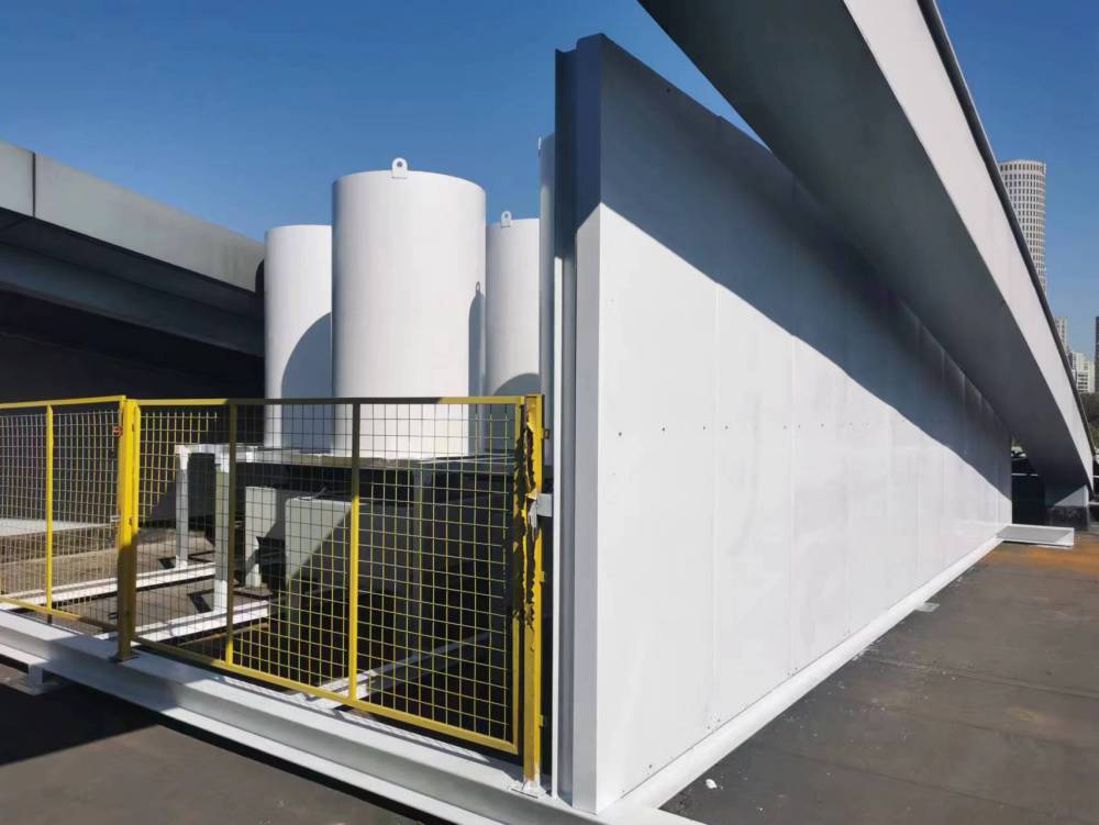
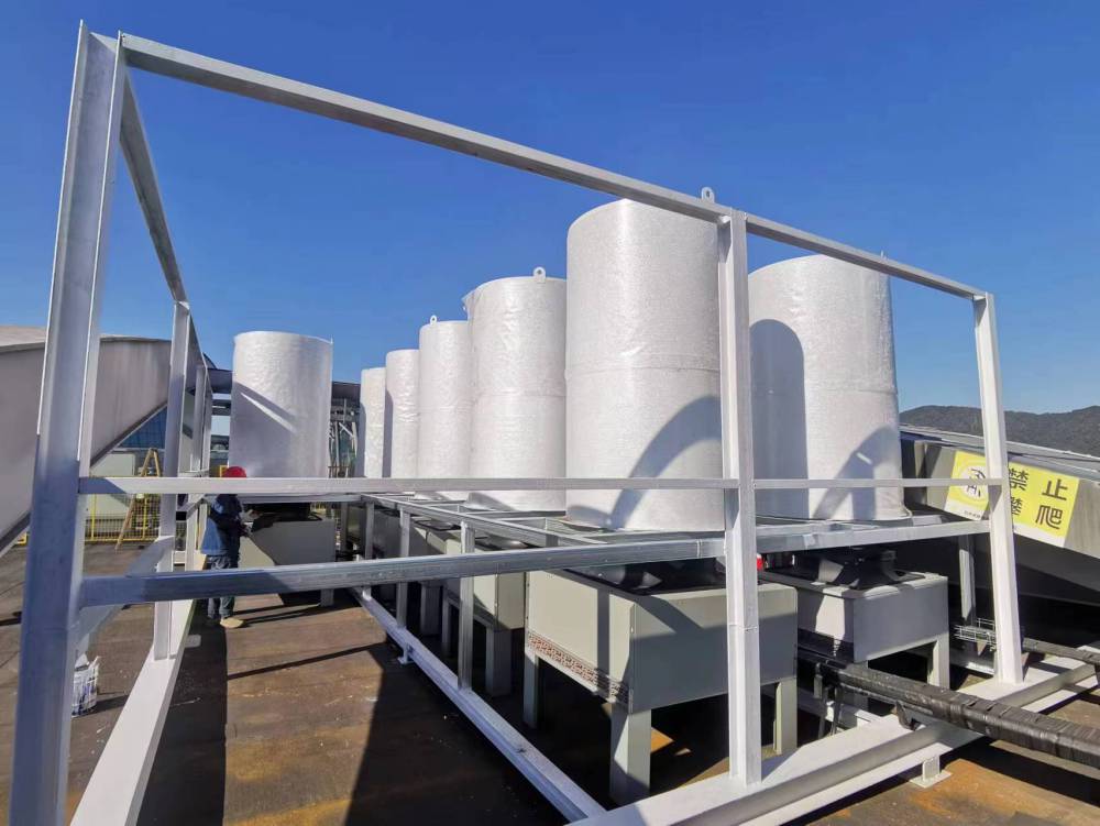
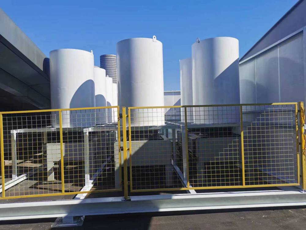


Zhejiang Hangzhou Sound Absorbing and隔音Barriers, Soundproof Panels, Acoustic Materials, Transparent Soundproof Panels, Semi-Closed Sound Barriers, Closed Sound Barriers, High-Efficiency Noise Reduction, Excellent Material, Significant Soundproofing Effect
Zhejiang Hangzhou Transparent Soundproofing Panels, Sound Absorbing and Blocking Screens, Noise Reduction and Environmental Protection, Semi-Enclosed Sound Barrier, Material Upgrade, High-Efficiency Sound Absorption and Noise Reduction, Fully-Enclosed Sound Barrier, Hangzhou Made, Professional Sound Absorption and Noise Reduction Choice, High-Quality Transparent Soundproofing Panels, Significant Soundproofing Effect, Zhejiang Hangzhou Soundproofing Screens, Sound Absorbing Materials, Eco-Friendly Noise Reduction, Durable Sound Absorption, Hangzhou Quality Assurance, Fully-Enclosed Sound Barrier, Soundproofing and Noise Reduction, High-Efficiency Sound Absorption Materials, Transparent Soundproofing Panels, Eco-Friendly Materials, Noise Reduction Upgrade, Hangzhou Transparent Soundproofing Panels, Sound Absorbing and Blocking Screens, Craftsmanship, Semi-Enclosed Sound Barrier, Sound Absorption and Noise Reduction, Hangzhou Brand Recommended
Design Key Points for Sound Absorbing and Soundproofing Barriers
1. Sound Barrier Insertion Loss Calculation
The insertion loss of noise barriers primarily depends on the diffraction attenuation ΔLd, transmission reduction ΔLt, and reflection reduction ΔLr of the barriers, which is the noise reduction amount NR of the noise barriers:
NR=△Ld-△Lt-△Lr (1)
Considering the effects of other obstructions and ground absorption, the actual insertion loss of the sound barrier is:
IL=△Ld-△Lt-△Lr-MAX(△Ls,△LG) (2)
△Ls represents the diffraction sound attenuation that may occur between the sound source and the receiving point due to other barriers or obstructions. △LG represents the attenuation caused by ground absorption. MAX indicates taking the greater of △LS and △LG, as both generally do not coexist simultaneously.
1.1 Determination of Diffraction Sound Attenuation △Ld
Infinite Length Line Source, Infinite Length Sound Barrier:

(3)
In the formula: f - sound wave frequency, Hz.
δ = A + B - d is the path difference, m.
Speed of Sound, m/s.
Figure 1 shows the path of sound wave propagation:

Figure 1: Acoustic Propagation Path
Finite-length line sound source and sound barrier: The diffraction sound attenuation is still calculated using Equation (3), and then corrected according to Figure 2. The corrected ΔLd depends on the shielding angle β/θ.

Figure 2: Correction Diagram for Limited-Length Acoustic Barriers and Linear Sound Sources
1.2 Determination of the Transmission Sound Reduction ΔLt
The transmitted sound reduction amount ΔLt is calculated using the following formula:
ΔLt=ΔLd+10lg(10-ΔLd/10+10-TL/10) (4)
1.3 Determination of the Reduction in Reflective Sound Level ΔLr
The reduction in reflected sound depends on the height of the sound barrier, the receiving point, and the sound source, the distance from the receiving point to the sound barrier and the sound source, as well as the noise reduction coefficient NRC of the sound-absorbing structure of the sound barrier on the inside of the sound source.
2. Barrier Structure Stability Design (Examples of Parameters)
2.1. Due to the light upper structure of the sound barrier, the vertical force on this part is considered zero, which is a favorable condition:
ΣN=0.
2.2. Wind load takes the 100-year return value of 0.5 KN/m² or 50 kg/m², i.e., q0 = 50 kg/m².

Figure 1: Overall Stress Analysis
Body coefficient is 1.3.
The height variation coefficient is 1.17.
Then, q1 = 1.3 × 1.17 × 0.5 = 0.76 KN/m² = 76.05 kg/m².
Then, q = 0.76 × 2.5 = 1.9 KN/m.
2.3. Calculation of tensile strength for anchor bolts embedded at the base of columns

Figure 2: Column Load Analysis
As shown in Figure 2, with the wind pressure design value Wk = 0.76 KN/m2, it converts to the linear load qk = 1.9 KN/m. For a cantilever beam, it follows:
Mmax=ql2/2=1.9×10.32/2=100.8KN·m,
R拉 = Mmax / 0.4 = 252 KN, assuming the three bolts on the far right, M30×1000, bear the load, each would be subjected to 84 KN. In reality, the two middle M30 bolts also bear force, meaning the actual load per bolt is less than 84 KN. However, even at 84 KN per bolt, the M30×500 chemical anchor bolts have tensile and shear strengths over 100 KN, let alone the M30×1000 embedded bolts.
2.4. H-Section Steel Column Strength Calculation
H-beam 300×200×8×12×12 (Q235): Ix=11400×10^4 mm^4, Wx=779×10^3 mm^3
Root: σmax = Mmax/Wx = 100.8 × 10^3 × 10^3 / (779 × 10^3) = 129.4 N/mm² ≤ 205 N/mm², meets requirements.
2.5. Stability Calculation
Q=q×12=2280=2.28t

K≤1.3K0
W1 (Self-weight wall) = 0.5 x 2 = 1.0 t/m
W2 (concrete wall) = 2.5 x 2.22 = 5.55 t/m
W3 (soil self-weight) = 6 x 2 = 12 t/m³
Σw0=18.55t,ΣW=18.55×2.5=46.4t
1.3×Tipping Moment = 2.28×1.3×9 = 26.7
The overturning moment is 46.4 x 1.5 = 69.6 > 26.7
The sound barrier foundations have good stability.