


With the rapid development of solar photovoltaic equipment, the roof load-bearing capacity inspection of solar PV systems has become the most critical concern in project development.
Recently, news of solar power stations collapsing due to heavy snow has been frequent, and issues with roof load-bearing have once again caught attention. According to the current national code for structural load of buildings...
Requirements: Any new large equipment, such as solar photovoltaic roof installations, must be subject to load testing and evaluation by a third-party building safety assessment agency.

There are two common methods to determine the roof-bearing capacity:
One method involves collecting structural data of the building through on-site inspections, followed by computer modeling and analysis to approximately determine the load-bearing capacity limit of the roof.
Workload is relatively light, highly applicable, and cost-effective, making it a widely used method at present. Another approach is to conduct load-bearing tests.
This experimental method is commonly used in stringent testing projects, such as the load-bearing capacity testing of floors in areas where bank safes are placed, requiring accuracy and thoroughness.
Understanding the floor load-bearing capacity is generally achieved through this method. Specifically, it involves setting up observation points at the bottom of the floor to measure the deformation of the floor and beams.
Apply equal loads (such as water, sandbags, etc.) in batches, sequentially stacking at equal weights on the floor, closely monitor the deformation of beams and slabs, until the deformation value approaches the standard.
At a specified larger allowable deformation value, stop loading; the load weight at this point is the load-bearing capacity limit of the floor.

With the country's support for the new energy industry, an increasing number of photovoltaic projects are being vigorously constructed, making the space for photovoltaic placement an urgent issue to address.
Currently, photovoltaic installation primarily involves two major directions: one is placing them on open ground, such as desert regions, and the other is installing them on the roofs of buildings. For installations on...
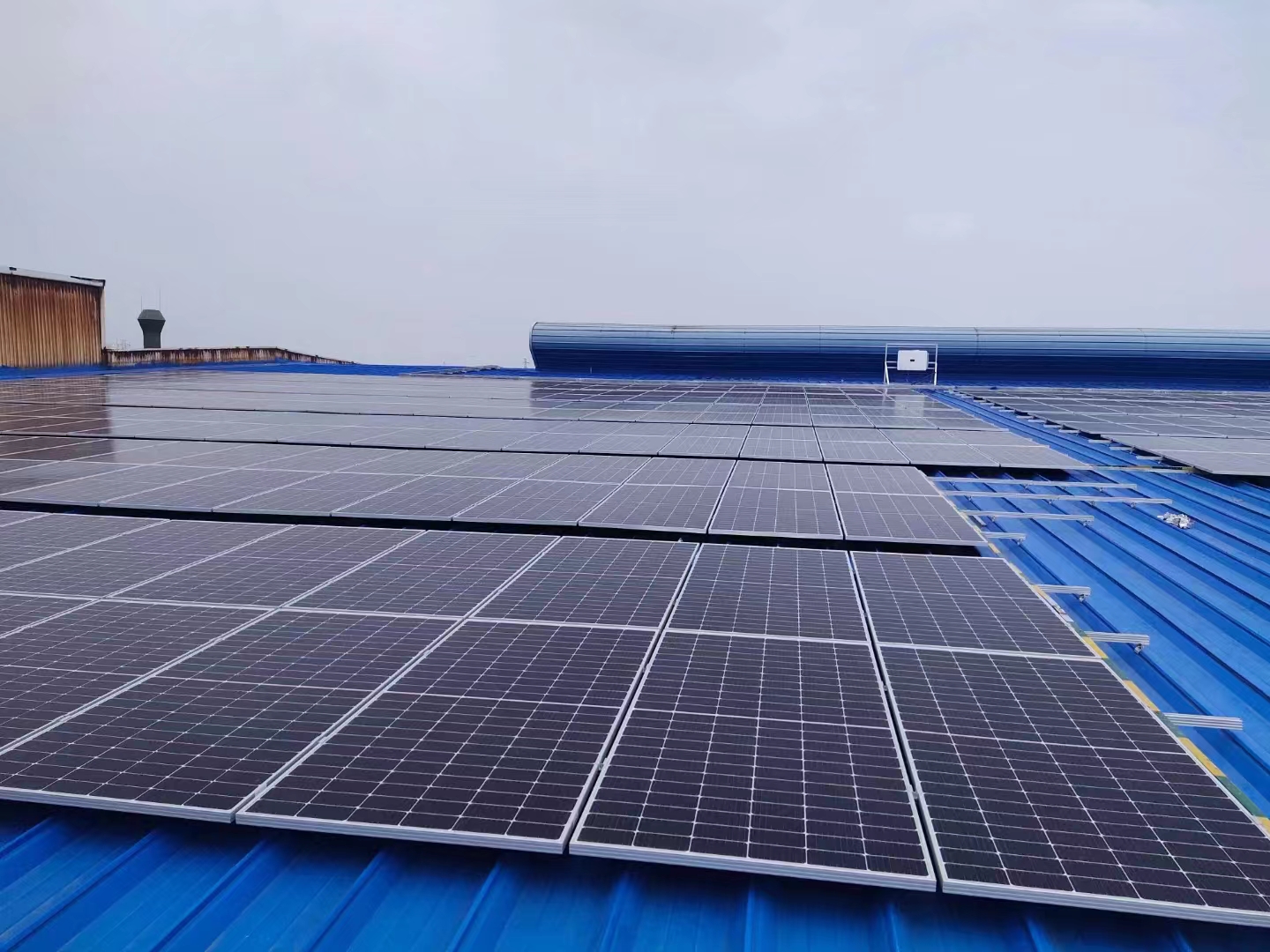
Photovoltaic installations on building roofs require ensuring that the roof's load-bearing capacity meets the requirements before placement; otherwise, it may lead to serious accidents such as building collapse.
Solar panels typically weigh around 20 kg per square meter. Generally speaking, installing them on concrete roofs poses no significant issues, but for steel structures,
Strict inspection and identification must be conducted before execution. The reason is: generally, the roofs of steel structure buildings are non-accessible roofs, and the design values of the live load on the roof are originally...
The size is relatively small; in southern regions without snow, it's generally 0.5 kN/㎡, while in northern areas, snow load must be considered, usually around 0.7 kN/㎡. Primarily, it's an addition of...
The weight of photovoltaic panels can significantly lead to insufficient load-bearing capacity, potentially causing safety accidents. Our company's primary business scope currently includes: house quality and safety assessment,
Deterioration Assessment, Integrity Level Evaluation, Steel Structure Engineering Inspection, Surrounding Construction Impact Assessment, Property Valuation, Seismic Resistance Evaluation, Post-Disaster Assessment
Legal Appraisal, Historical Preservation Appraisal, Industry Certification Handling

A single-story factory structure is a complex spatial force system composed of various components, which can be divided into load-bearing structural components and protective structural components.
Three major components of the support system.
Load-bearing structural elements: Directly bear loads and transfer them to other components, including roof structures, column frames, crane beams, and foundations, etc.
Sheathing components: mainly longitudinal walls, gables, connecting beams, wind-resisting columns, etc., designed to bear self-weight and wind loads acting upon them.
Supporting System: A crucial component that links rafters, skylight frames, columns, etc., to enhance the overall structural integrity.
1. There are many types of loads for portal frame structures. Earthquake loads belong to horizontal loads and have a relatively small impact on the rigid frame, but they should not be overlooked.
2. The primary horizontal load is due to wind. The wind load acts horizontally on the gable wall, with part of the load transferred to the roof's horizontal support system via wind-resisting columns.
A portion of the load is transferred to the inter-column supports via the load-bearing columns.
3. This distributes the load to both the horizontal lateral supports and the vertical column-to-column supports, transferring the load. The lateral stability of the portal frame is crucial.
It should be straightforward for vertical loads.
4. Roof panel purlins support and hang the self-weight of the rigid frame, which is then transferred to the foundation through the rigid frame columns. Look at the type of joint you choose to use: rigid or hinged.
Just received; capable of transmitting bending moments and shearing forces, while the hinge joints can only transmit shearing forces.

The prospects for the development of rooftop photovoltaics are immense: Distributed photovoltaic power generation, as a new mode of power generation and consumption, boasts the advantages of on-site generation and on-site grid connection.
The characteristics of "local conversion and local usage" have garnered extensive attention and promotion from various countries in recent years. As of the end of 2010, the cumulative installed capacity of distributed photovoltaic power generation
The capacity is 23.4GW, accounting for 66.8% of the cumulative installed capacity of photovoltaic power generation systems in the same period, indicating that distributed generation is the mainstream application of photovoltaics within the scope.
Therefore, in recent years, our country has regarded distributed photovoltaic power generation as a key measure for developing clean energy, resolving excess capacity, and combating air pollution.
Continuously emerging policies are encouraging promotion. Currently, distributed photovoltaic power generation systems are generally installed on building roofs, while industrial factory buildings are mostly low and narrow.
Flat factory buildings with high electricity demand and high electricity prices have become ideal locations for large-scale promotion of distributed photovoltaic power generation. As of the end of 2006,
China boasts 1,568 various economic development zones (including high-tech zones, industrial parks, etc.), with a planned area of 9,949 square kilometers and a building density
Approximately 29.28% (based on the 2012 industrial park survey results), this would equate to about 3,000 km2 of industrial rooftops suitable for installing photovoltaic systems.
At an estimated 10㎡ per kW of photovoltaic array, the installed capacity can reach 300GW, indicating a very promising market outlook. On the other hand, China's distributed photovoltaic...
The construction standards for power generation are not unified, and the insufficient load-bearing capacity of different types of roofs leads to concerns about the operational quality of existing photovoltaic projects.

Main contents of the structural steel workshop roof photovoltaic load-bearing inspection:
(1) Factory Usage Survey & Review of Architectural and Structural Drawings
Firstly, investigate the historical usage of the factory building, understanding the house's condition during use.
Have you experienced major disasters, have the loadings increased, or have there been significant changes in the usage functions?
On the basis of familiarizing and mastering existing original drawings and materials, through
On-site comprehensive surveying and verification (foundation excavation), establishment of architectural plans, elevations, sections, typical structures, foundation plans, structural plans, and typical structural components
Cross-sectional and node construction technical information, particularly the connection and reliability of the added structure to the original structure.
(2) Material Strength Testing
To determine the compressive strength of the concrete components of the inspected house, a ZC3-A type concrete is adopted based on the actual on-site conditions of the inspected house.
Rebound meter, ascertaining component strength in accordance with the "Technical Code for Concrete Compressive Strength Testing by Rebound Method" (JGJ/T23-2011), further based on
"Concrete Structure Reinforcement Design Code (GB50367-2013) makes an age correction to the concrete for this component, determining the current age concrete compressive strength grade of the said element."
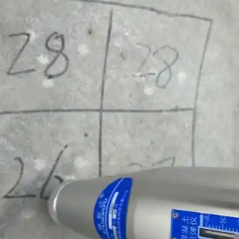
Random inspections will be conducted at a rate of 30%.
(3) The content and methods of structural material testing mainly include:
Concrete Strength – Non-destructive testing by rebound method; core drilling method for verification when on-site conditions are available.
Reinforcing bars - Surface hardness method used.
Detection of appearance quality defects and structural damage
Component surface defects, including: columns, beams, board supports, and roof structure
Systems, protective systems, etc.
Comprehensively inspect the appearance defects of components, such as deformation, damage, rust, and warping. Document them in both photo and written form.
Test results can be recorded as severe defects and general defects, with additional details such as the location and extent of severe defects recorded for reference during resistance calculations.
Consider the impact of defects.
For rusty rods, areas prone to accumulate dust and water, locations affected by alternating dry and wet conditions, and concealed areas, apply a corrosion-resistant coating first.
Inspection for damage, if the corrosion-resistant coating is severely damaged, conduct a rust level check and use a caliper or ultrasonic thickness gauge for necessary measurements.
(4) Component Deformation Inspection
The verticality of vertical components is a crucial indicator for the performance of the components, and it also affects their load-bearing capacity.
(The influence of secondary bending moment), therefore, the measurement of column inclination is very necessary. On-site, the Leica TCR1202 total station can be used in conjunction with the steel tape projection method.
Measure the inclination of the column, with the sampling ratio following the minimum sample size required for structural sampling inspection.
Measurement of girder deflection during roof photovoltaic load-bearing test of steel structure factory shed
Method 1: First, place the level ruler vertically on the beam flange measurement point or invert the ruler to place it on the bottom flange measurement point, then read the level instrument's measurement.
The连线 between the two end measuring points forms the baseline, from which the relative deformation of the intermediate measuring point on the beam is calculated. Additional measuring points should be added if supports are encountered.
Method Two: Utilize prismless radiometric technology with a total station to directly measure the flange points on or below the beam, then use the line connecting the beam's end point measurement points as the baseline.
Calculate the relative deformation at the midpoint measurement point of the beam. Increase measurement points if supports are encountered.
The deflection measurement of this horizontal member should be carried out using a level or a laser distance meter.
Conduct inspections, select three points on the component support and mid-span as measurement points, measure the relative height difference between the component support and mid-span, and use this relative height difference to calculate the component's
Deflection. The beam deflection is measured using a Leica TCR1202 total station, with the sampling ratio in accordance with the minimum sample size for structural sampling inspection.
(5) Factory Building Settlement and Overall Tilt Measurement
Measure column base elevation using a Leica NA2 leveling instrument, inspect for uneven settlement of the factory building, foundation
Are there any insufficient bearing capacity issues? On-site, check for the presence of original level control points, and use the window sills, floors, or parapets as reference planes according to the on-site conditions.
Reference points should be set at the corners of the object, large turning corners, and every 5 to 10 meters along the outer wall or at each column, to measure the relative uneven settlement of the factory building.
Measure the horizontal height at the ends and mid-span of concrete or steel beams using a total station, and calculate the mid-span deflection of the beam by utilizing the horizontal height differences at the measurement points.
Measure the inclination of the corner edges of steel columns using a theodolite or total station, and calculate the column's inclination rate using the horizontal displacement difference.
(6) Weld Seam Quality Inspection
Components in critical load-bearing areas (including bearing equipment piping), connection welds, beam and column joints, steel supports connected to beams and columns
Connectivity welds, beam-column component joints, and other types of joints are subject to random inspection. The specific inspection locations are determined based on the ground-down areas on-site.
The specific inspection process and methods are as follows:
Ultrasonic inspection technology and process for load-bearing roof inspection of steel structure factory buildings with photovoltaic systems
1) Ultrasonic Testing Technology Grade
a) Ultrasonic Testing Technology Grade Selection
Ultrasonic Testing
Technical grades are divided into three inspection levels: A, B, and C. The selection of ultrasonic inspection technical grade should comply with relevant regulations and standards for manufacturing, installation, and in-use.
Design Pattern Specifications.
b) Requirements for different testing technology levels
⑴ Grade A is suitable for butt welding joints with base material thickness of 8mm to 46mm. A probe with a K value can be used.
Inspections are conducted on the single-side, single-surface of the butt-welded joint using direct wave and one-time reflection wave methods. Generally, there is no requirement for the detection of transverse defects.
⑵ B-Grade Inspection:
Ⅰ) When the thickness of the base material is between 8mm and 46mm, a K-value probe is generally used for both direct wave and first reflection wave methods at the butt welding joint.
Inspection conducted on both sides, single-sided and double-sided.
Ⅱ) When the thickness of the base material is greater than 8mm to 46mm, a K-value probe is generally used with the direct beam method on both sides of the焊接 joint.
Perform inspections; where geometric constraints are present, inspections can be conducted using two K-value probes on either the single-sided double-face or double-sided single-face of the weld joint.
Ⅲ) Base Material Thickness
For diameters greater than 120mm to 400mm, generally, two K-value probes are used to perform detection on both sides of the welding joint using the direct wave method. The refractive angles of the two K-value probes.
The difference should not be less than 10o.
Ⅳ) Horizontal defect detection should be conducted. During the test, the probe should be positioned at the edges of the welding joint, aligned with the centerline of the weld.
Perform a diagonal parallel scan in two directions at 100° to 200°.