


Product Details
I. Overview:
The ball cleaner is a device used to effectively clean the condenser cooling tubes of steam turbine generators during operation. The performance of this device directly impacts the cleanliness of the condenser and its heat transfer efficiency. Its application range is quite extensive, covering not only condensers of steam turbines but also the cooling tube cleaning of fixed tube sheet heat exchangers in the oil, chemical, and other industries. Under continuous operation without reducing load, this device can be put into use at any time, maintaining the cleanliness of the cooling tubes, extending their service life, reducing labor intensity, and is essential for improving the economic benefits of power plants and ensuring the safe operation of condensers.
Our factory's rubber ball device is a replacement product for other rubber ball cleaning devices available on the market. The main components, the secondary filter and the ball collection net, come in two current models. It boasts the following features:
1. Innovative and rational design structure; 2. Easy to operate; 3. High gel ball recovery rate (≥96%); 4. Strong secondary filter mesh filtration capability.
Section II: Ball Cleaning System Diagram
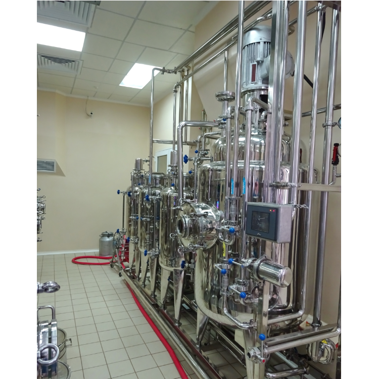
The rubber ball cleaning system consists of a secondary filter, ball collection net, ball loading chamber, rubber ball pump, separator, valves, pipelines, and electrical control unit.
III. Working Principle:
Select an appropriate sponge rubber ball, with a wet diameter slightly larger than the cooling tube's internal diameter (about 1-2mm) and a wet density similar to water. Place the balls into the ball chamber through the manual access hole, aiming for approximately 10% of the copper tube count in the condenser water chamber. Then, start the ball pump and open the ball valves at both ends of the system. The balls are carried into the condenser water chamber by the water flow with slightly higher pressure at the circulation water inlet. As the balls are a soft, elastic, porous material, they are compressed through the cooling tubes under the pressure difference between the water flow's inlet and outlet, scrubbing the internal diameter. The dirt on the tube walls is carried away with the water flow. The balls then enter the collection net through the outlet pipe, where they are separated by the net plate and extracted by the ball pump back to the ball chamber, repeating this process for continuous and automatic cleaning of the condenser cooling tubes.
IV. Components of the Gel Ball Cleaning System:
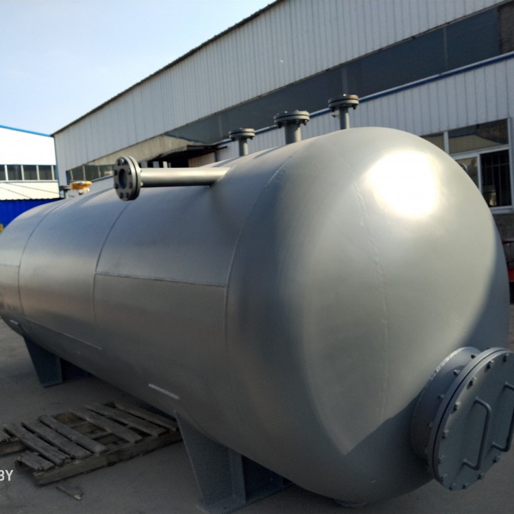
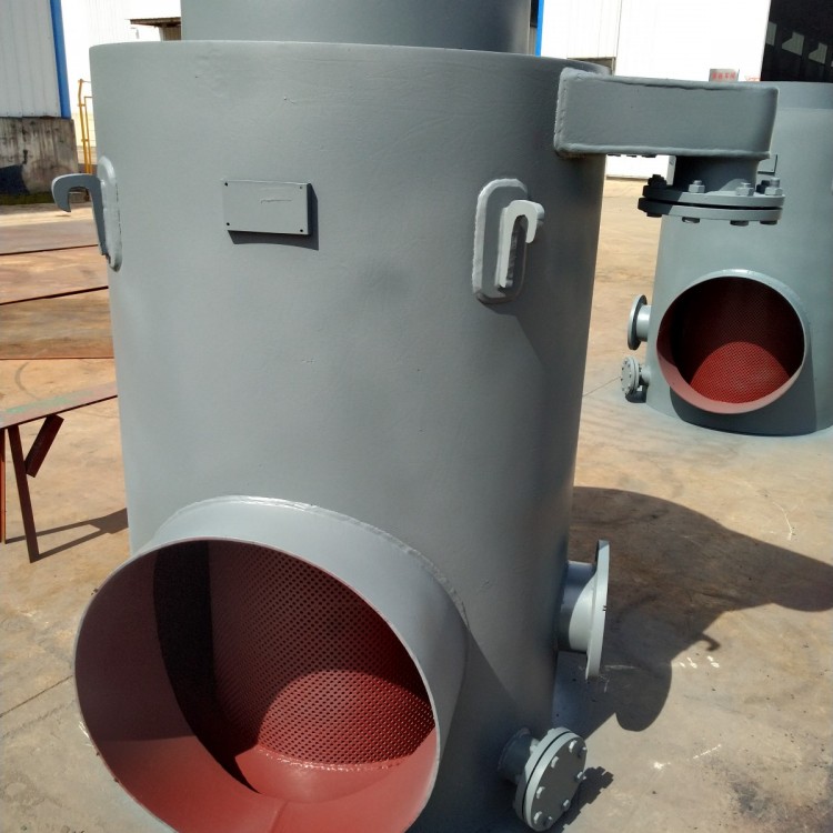
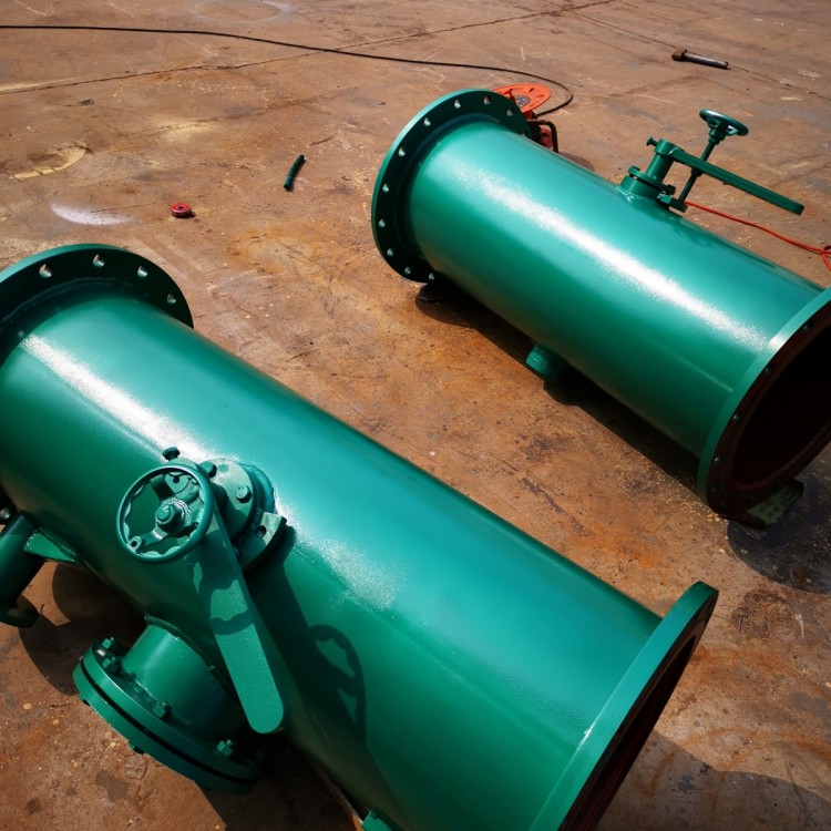
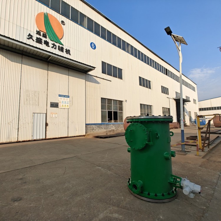
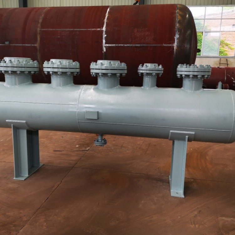
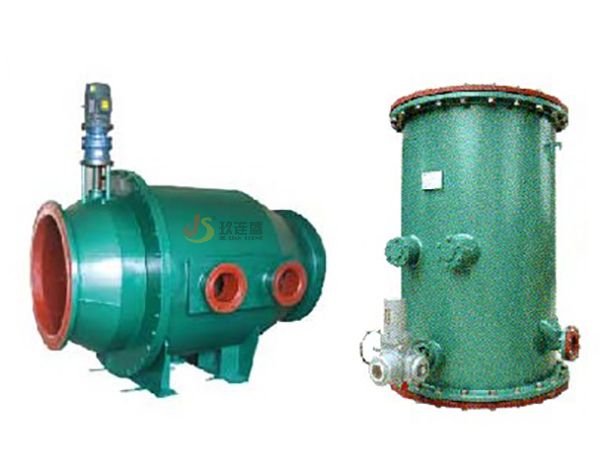
1. Secondary Filter: The secondary filter is one of the main equipment in the cooling water purification system, removing all debris larger than 6mm. It plays a crucial role in ensuring the smooth flow of rubber balls and the normal operation of the condenser. For detailed working parameters and other information, refer to the "New Electric Rotating Reverse Jet Secondary Filter" manual.
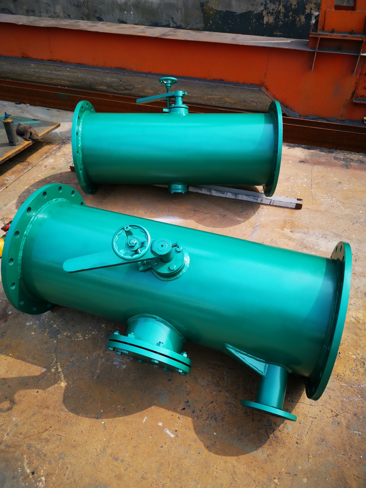
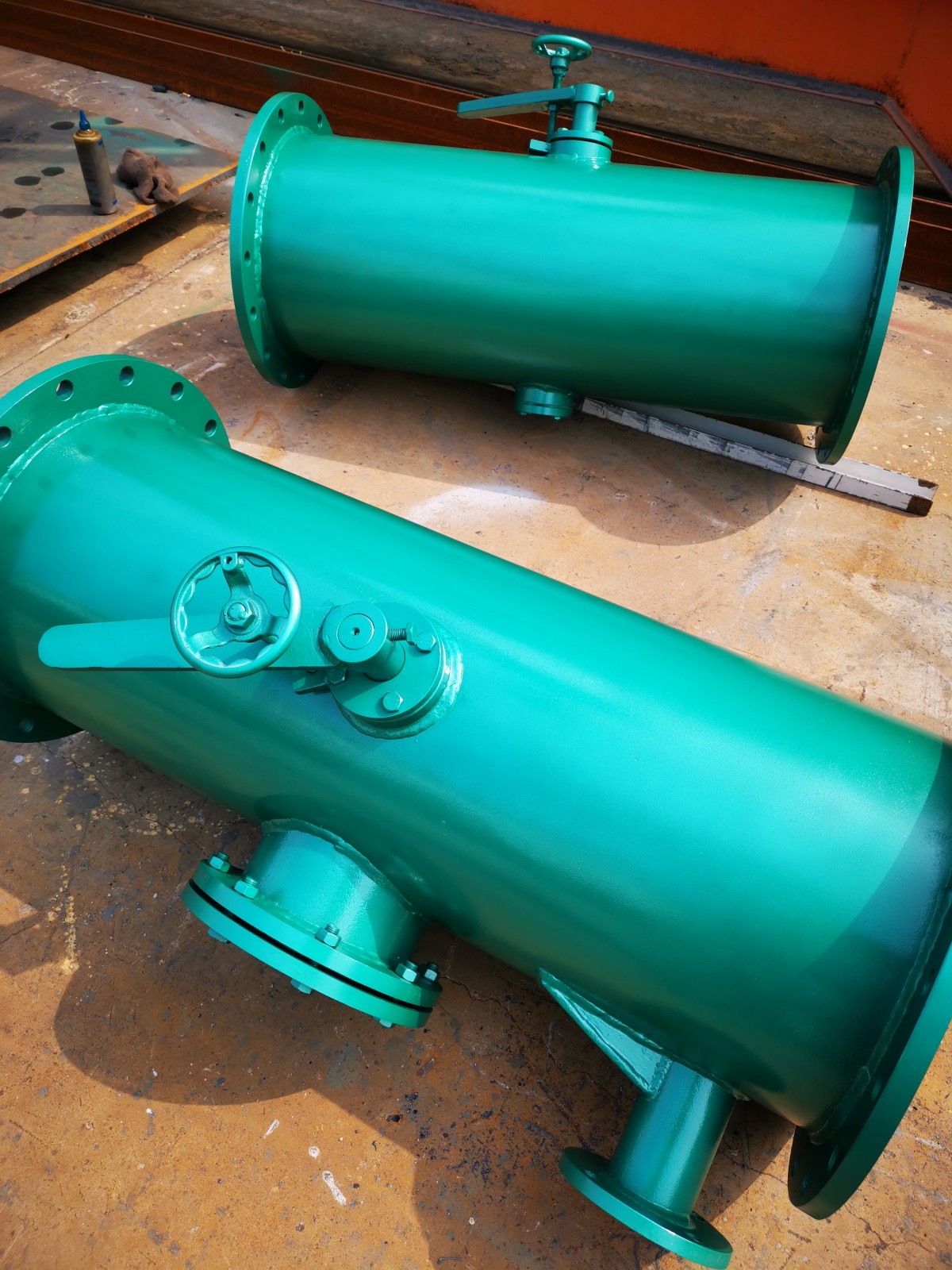
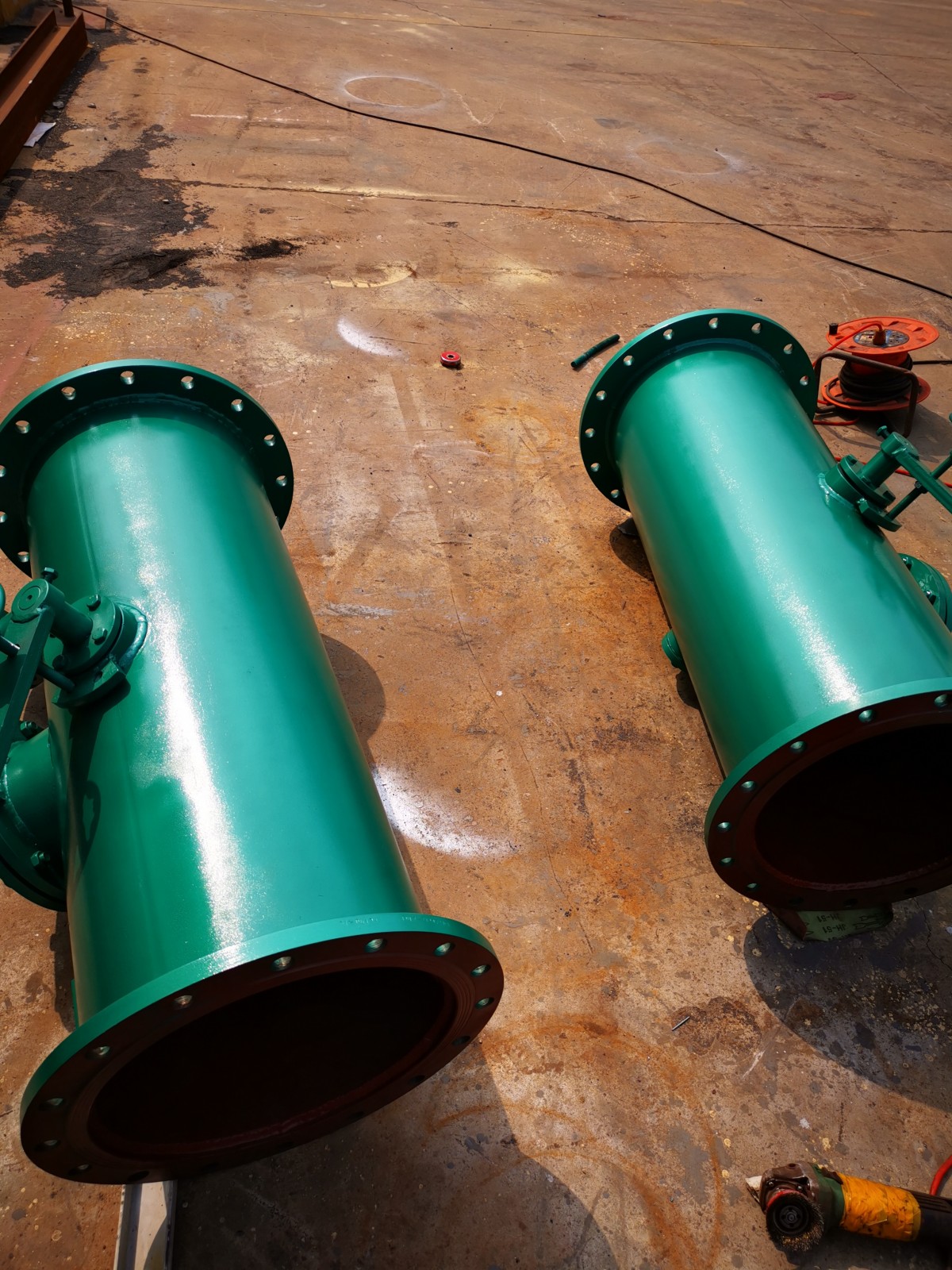
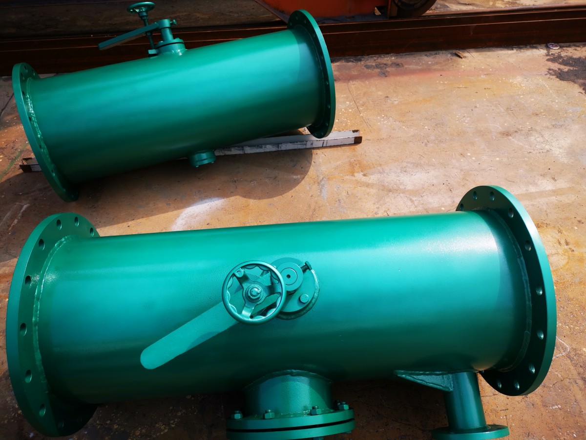
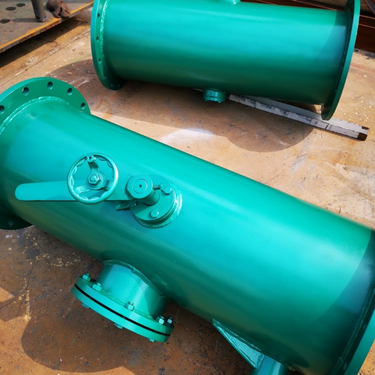
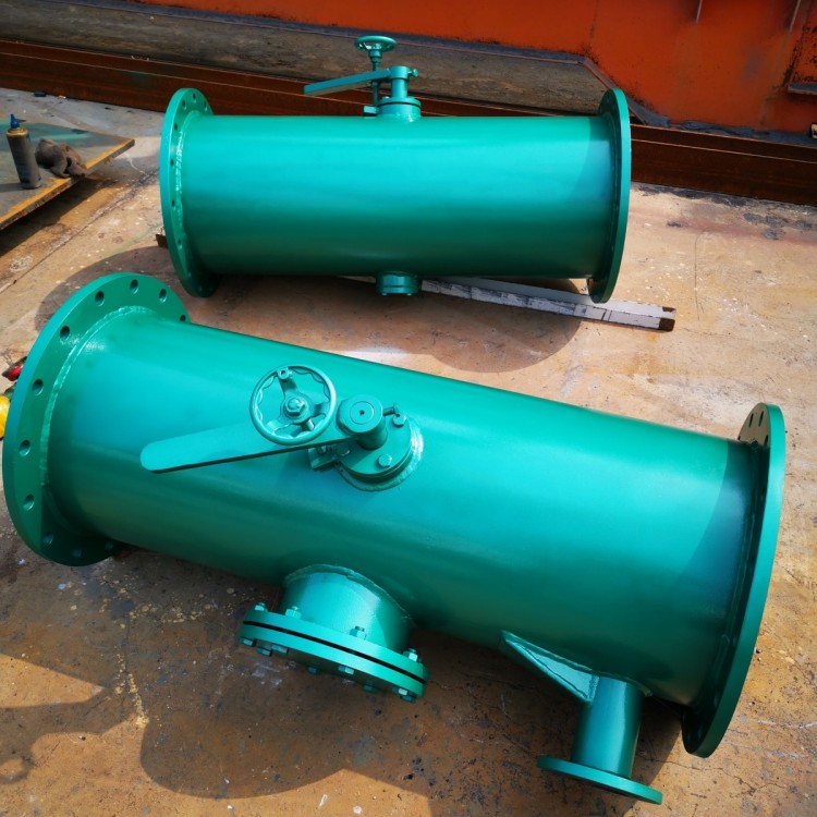
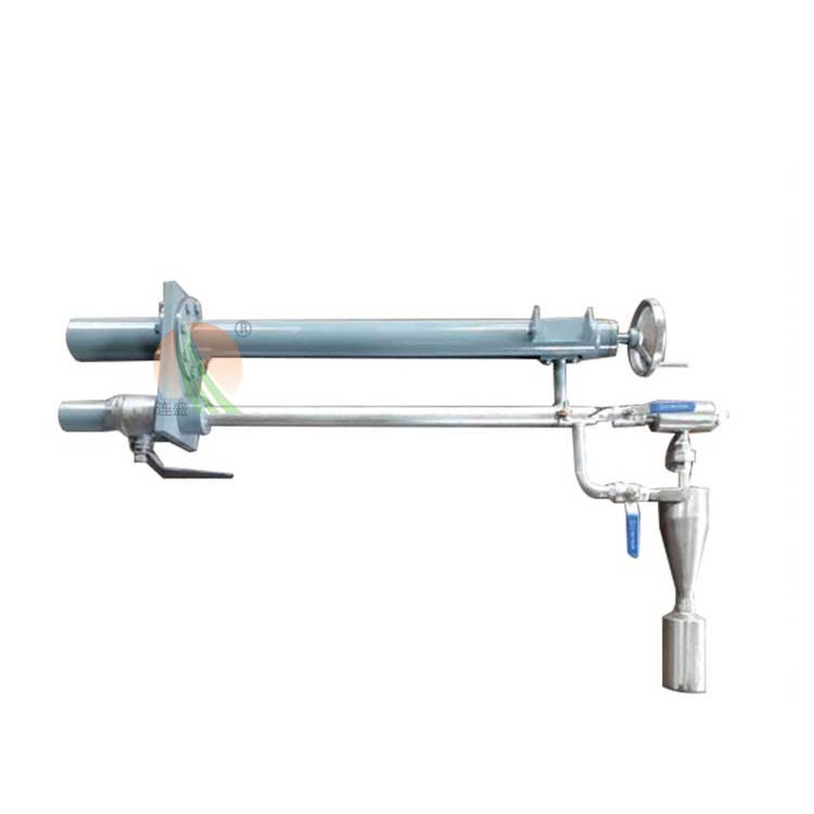
2. Ball Catcher: The ball catcher is a crucial component of the rubber ball cleaning system, installed on the condenser outlet pipe section. Its function is to separate the rubber balls from the cooling water, ensuring no balls are lost or jammed. After the balls are collected, they are guided out through the outlet pipe and returned to the ball-loading room. Our factory's ball catcher features the latest design, with its grate plate being rotatable. When the rubber ball unit is in operation, the grate plate is positioned for ball collection. When the cleaning unit is not in use, the grate plate can rotate to align with the water flow direction, reducing water resistance and also serving to clear debris from the grate plate.
The rotation positioning of the mesh board is executed by an electric actuator (the small ball-catching net is manually controlled). Whether the mesh board is in place is a crucial factor in ensuring the ball-catching efficiency of the net.
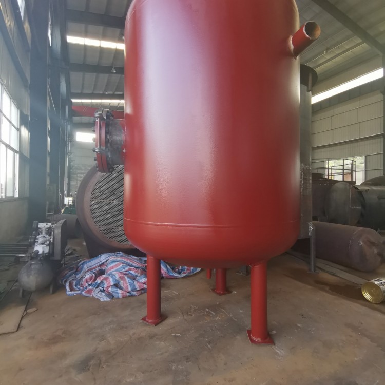
3. Ball Loading Room
The ball loading room is a device in the胶球 cleaning system for adding, retrieving, storing balls, and observing the ball circulation. It is divided into Type I and II based on the storage capacity of the balls, and into electric and manual types according to the user's requirements. When the switch valve controlling the operation status of the ball loading room is set to the "feed ball" position, the balls can circulate freely and continuously within the system. When the switch valve is set to the "collect ball" position, the balls are blocked within the ball loading room, while the cooling water can still pass through. All balls introduced into the circulation return to the ball loading room.
4. Spherical ball pump
The rubber ball pump is the power source in the rubber ball cleaning system that continuously circulates the balls. The water flow from the ball intake net, after passing through the rubber balls, increases the pressure head and is sent into the cooling water pipes. This pump is a fixed, trouble-free centrifugal pump, featuring non-blocking, non-crushing of balls, and minimal wear on the balls. Depending on different operating conditions, different parameter specifications of rubber ball pumps are selected. For small condensers and heat exchanger systems, a low-flow pump should be chosen to reduce hot water backflow; for systems with long rubber ball conveying pipelines and significant resistance losses, a high-head pump should be selected to ensure normal ball circulation.
5. Operation Control Cabinet (CGK-Ⅱ)
(1) Employed with an HMI touch screen control, it's more advanced and rational with a low failure rate. (HMI human-machine interface touch screen and PLC)
(2) Achieve precise location control for more accurate and thorough detection, ensuring a high recovery rate of the balls. The entire process is automated. Long-distance control (operation and monitoring) via a single cable is achievable.
6. Divertor
A diverter valve is a three-way (pipe) valve. By switching the guide plates, it allows the ball to enter the condenser side that requires cleaning. It can also be used as a three-way pipe for the convergence of the ball collection net outlet pipe and the分流 of the ball intake pipe.
V. Installation Instructions and Precautions:
Prior to commissioning the rubber ball cleaning unit, first thoroughly clean the condenser water chamber and the interior walls of the copper tubes, and replace any copper tubes with cracks or deformation in the inner diameter one by one to ensure smooth passage of the rubber balls.
(2) Seal off all dead corners of the condenser one by one to prevent the hiding of rubber balls, which can affect cleaning efficiency and the recovery rate of rubber balls.
(3) The system pipeline layout should be simple, short, and straight, with as few bends as possible.
(4) Select the ball pump reasonably; ensure it has sufficient flow rate, and the outlet pressure should be slightly higher than the circulating water pressure (about 0.02 MPa or more).
(5) Regularly inspect the ball chamber's胶球quantity, continuously replenish, and meet cleaning requirements.
(6) Regularly inspect the ball recovery rate; for instance, if the recovery rate is low, investigate the following three aspects.
Is the ball collection grid panel in the collection position and properly in place?
b. Is there any debris in the condenser water chamber, blocking the cooling tube openings, and hindering the passage of the rubber balls?
c. Is the outlet pressure of the ball pump normal?