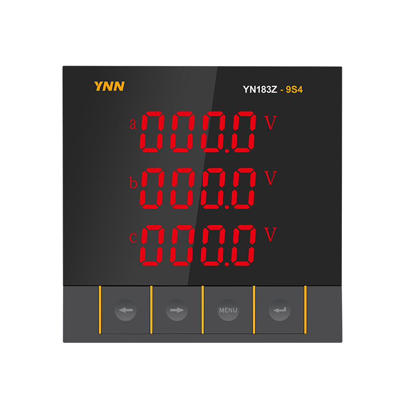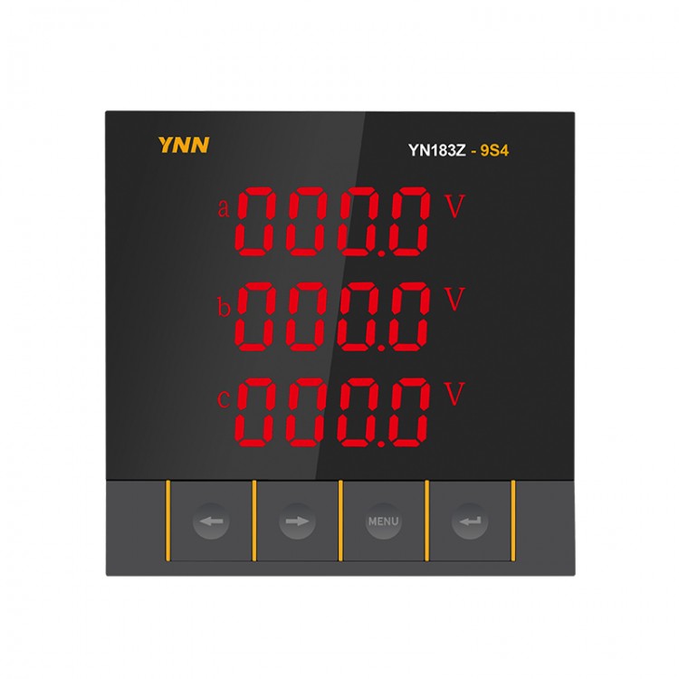


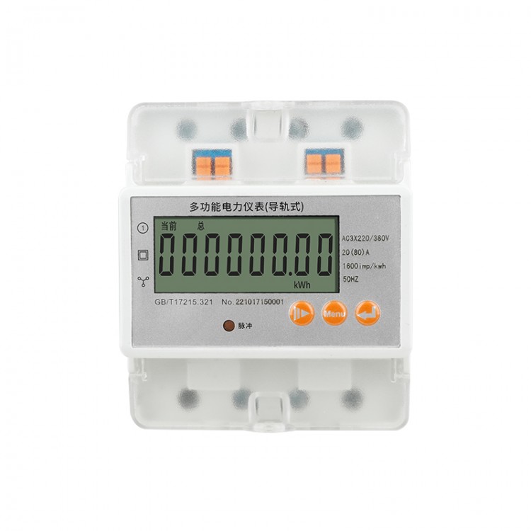
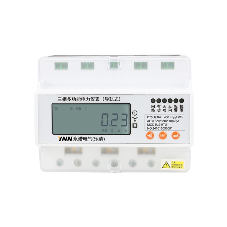

A multifunctional electric power instrument is a network-based multifunctional electric power instrument with programmable measurement, display, digital communication, and electrical energy pulse transmission output capabilities. It can perform power consumption measurement, electrical energy metering, data display, collection, and transmission, and is widely used in substation automation, distribution automation, intelligent buildings, and internal power measurement, management, and evaluation within enterprises. It has a measurement accuracy of 1.0 class, features LED on-site display and remote RS-485 digital communication interface, and adopts MODBUS-RTU communication protocol or DL/T645-2007.
Product Features
Real-time Monitoring: Three-phase current, voltage, total active power, total reactive power, power factor, total apparent power, frequency, phase-wise active/reactive power, phase-wise power factor, reactive energy, active energy
LED Digital Display
Communication: 1-way RS485 communication function, MODBUS-RTU protocol or DL/T645-2007 protocol
Optional: 4-channel digital output, 4-channel digital input, 4-channel analog output
Application Fields: Industrial Manufacturing, Commercial Buildings, Integrated Factories, Substations, Public Utilities, etc.
Customization available, offering logo, appearance, and feature customization services for businesses.
Technical Specifications
| Performance | Parameters | ||
| Input Enter Measure Quantity Visible Please provide the Chinese content to be translated. | Internet | Three-phase three-wire, three-phase four-wire | |
| Voltage | Rated Value | AC25~500V | |
| Overload | Continuous: 1.2 times (consecutive) / 2 times rated value per second | ||
| Power Consumption | <0.4VA (per phase) | ||
| Impedance | >500KΩ | ||
| Accuracy | RMS Measurement, Accuracy Grade 0.5 | ||
| Current | Rated Value | AC25mA | |
| Overload | Continuous: 1.2x Instantaneous: 10x/1s | ||
| Power Consumption | <0.2VA (per phase) | ||
| Impedance | <2mΩ | ||
| Accuracy | RMS Measurement, Accuracy Grade 0.5 | ||
| Frequency | 45~65Hz | ||
| Power | Apparent Power, Active Power Accuracy 1.0 Class, Reactive Power Accuracy 2.0 Class | ||
| Electric Power | Four-quadrant measurement, active precision 1.0 class, reactive precision 2.0 class | ||
| Harmonic | Total Harmonic Content | ||
| Power Supply | Scope of Work | AC220V、AC/DC85~270V | |
| Power Consumption | ≤5VA | ||
| Output | Digital Communication | RS-485, MODBUS RTU protocol, or DL/T645-2007 | |
| Environment | Work environment | -10~55℃ | |
| Storage Environment | -20~75℃ | ||
| Safety | Pressure-resistant | Input/Power > 2kV, Input/Output > 2kV, Power/Output > 2kV | |
| Insulation | Input, output, power to housing > 50MΩ | ||
| Electrical Energy Measurement Range | 0~99999999 MWh, with both active and reactive energy measurement range Above this value, the electricity consumption starts counting from 0. | ||
| Enhanced Features | Switched Quantity Input | 4DI | |
| Switched quantity output | 4DO | ||
| Pulse Output | 1PO | ||
| Analog Output | 4AO | ||
| Rs485 Communication | 1-Channel RS485 | ||
| Harmonic | 2-63 times | ||
| Requirement quantity | Active Power, Reactive Power | ||
| Value statistics | Voltage, high current value | ||
| Optional accessories | 0.5S/0.2S | ||
| Serial Number | Standard | Register | |
| 1 | Rapid pulse train interference testing | GB/T.13729-2019.5.7.2(GB/T17626.4-2018) | 3 |
| 2 | Surge Interference Test | GB/T.13729-2019.5.7.3(GB/T17626.5-2019) | 3 |
| 3 | Power Frequency Magnetic Field Interference Test | GB/T.13729-2019.5.7.5(GB/T17626.8-2006) | 3 |
| 4 | Power Voltage Sag and Interruption Testing | GB/T·13729-2019.5.7.7(GB/T.15153.1-1998-A.1.5) | 2 |
Product Selection
Model Product Features | YN183E-9S4 | YN183Z-9H4 | YN183E-3S4 | YN183Z-3H4 | YN183E-AS4 | YN183Z-AH4 | |
| Measurement Parameters | Three-phase voltage | √ | √ | √ | √ | √ | √ |
| Three-phase Current | √ | √ | √ | √ | √ | √ | |
| Always have power | √ | √ | √ | √ | √ | √ | |
| Total Idle Power | √ | √ | √ | √ | √ | √ | |
| Power Factor | √ | √ | √ | √ | √ | √ | |
| Frequency | √ | √ | √ | √ | √ | √ | |
| Phase-Shifted Active Power | √ | √ | √ | √ | √ | √ | |
| Unbalanced reactive power | √ | √ | √ | √ | √ | √ | |
| Phase Power Factor | √ | √ | √ | √ | √ | √ | |
| Required Power (Active/Reactive) | Optional | Optional accessories | Optional accessories | Optional accessories | Optional accessories | Optional accessories | |
| Unbalance (voltage/current) | Optional accessories | Optional accessories | Optional accessories | Optional accessories | Optional accessories | Optional accessories | |
| Voltage High Value | √ | √ | √ | √ | √ | √ | |
| High Current Value | √ | √ | √ | √ | √ | √ | |
| Four Quadrant Power | √ | √ | √ | √ | √ | √ | |
| Harmonics 2-63 | √ | √ | √ | ||||
| Communication | RS485 | 1 lane | 1 lane | 1 lane | 1 lane | 1st Road | 1 lane |
| Expanded Features | Switched Input DI (optional) | 1-4 Channels | 1-4 Channels | 1-4 Channels | 1-4 Channels | 1-4 Channels | 1-4 Channels |
| Switched Output DO (Optional) | 1-4 Channels | 1-4 Channels | 1-4 Channels | 1-4 Channels | 1-4 Channels | 1-4 Channels | |
| Analog Output AO (optional) | 1-4 Channels | 1-4 Channels | 1-4 Channels | 1-4 Channels | 1-4 Channels | 1-4 Channels | |
| Dimensional Specifications | 96*96mm | 96*96mm | 80*80mm | 80*80mm | 72*72mm | 72*72mm | |
| Hole size | 91*91mm | 91*91mm | 76*76mm | 76*76mm | 67*67mm | 67*67mm | |
| Actual page is as per factory standard. | |||||||
Dimensions and wiring diagram

Panel Size (L × H) | Hole Size (S x Y) | Depth (N) |
96*96mm | 91*91mm | 47mm |
80*80mm | 76*76mm | 47mm |
72*72mm | 67*67mm | 47mm |
Installation Steps:
Remove the side installation card from the meter.
2) Drill a hole at the installation location with the corresponding hole size.
3) Insert the gauge into the hole, re-attach the mounting card to the meter from the back, and secure it.