


The normal speed self-inspection method simulates the actual operating conditions of firewater supply within a certain time frame. It tests the entire process of the fire pump starting and operating normally. However, improvements are needed in the pipeline design. It is crucial to prevent malfunctions of the by-pass solenoid valve; it must be opened during the self-inspection and promptly closed after completion. The low-speed self-inspection method does not require modifications to the fire pump's pipeline, but it only detects one phase of the fire pump's normal operating conditions. Fire pumps can be directly or indirectly started, with larger power pumps requiring indirect start. Indirect start methods include Y/Δ step-down starting, autotransformer step-down starting, and soft starter starting. During fire pump operation, the soft starter start is just an early stage, followed by normal operation. Frequency conversion methods also did not reach the industrial frequency stage. However, the low-speed self-inspection method still has some effect in preventing rust on fire pumps. Relative to this, it features low-frequency drive, slow rotation, and low power consumption operation of the equipment.
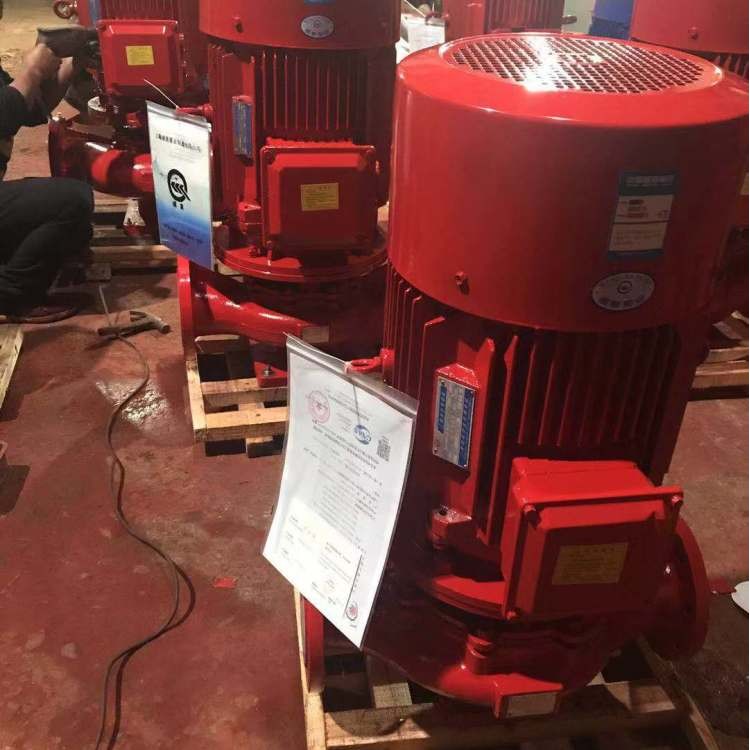
Inspect the normal operation of gate valves, check valves, and water hammer arresters on the water pipe line. Prior to the weekly operation of fire pumps, check that the main and backup power sources switch normally, verify the backup power source to ensure it can put the pump into normal operation within 30 seconds; and check if the standby pump can automatically switch and start running.
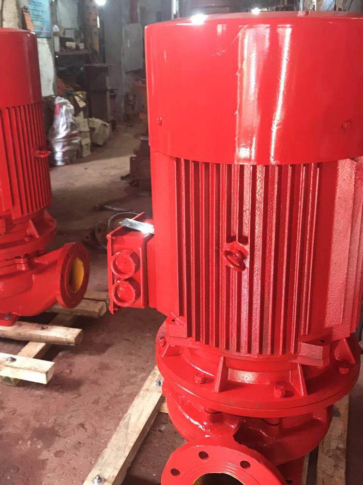
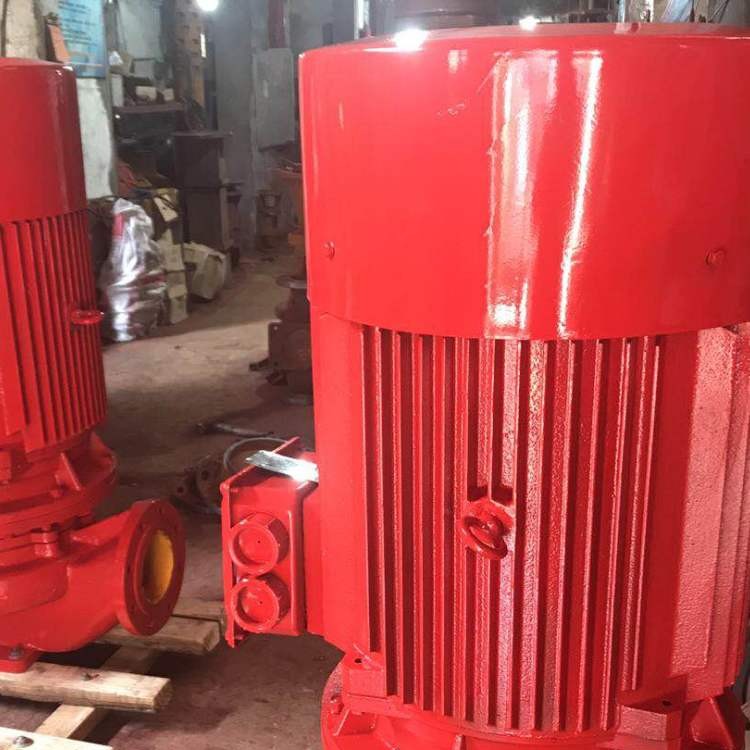
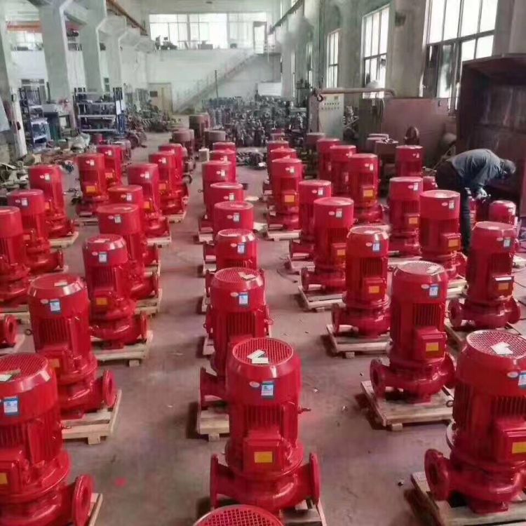
The fire suppression water booster system is composed of an air pressure water tank, pump, control cabinet, control instruments, pipe fittings, etc. The pump body is made up of the motor and the pump. The pump structure includes the pump body, impeller, pump cover, mechanical seal, etc., and the pump and motor are coaxial. The axial force of the pump is balanced by the impeller's balancing ring. The pump's inlet and outlet are on the same horizontal axis and have the same diameter specification. The pump is equipped with an installation base for easy installation and to enhance the stability of its operation.
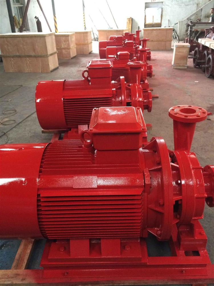
The XBD-L type single-suction single-stage fire pump consists of two parts: the motor and the pump. The pump and motor are coaxial, and the pump assembly includes the pump body, impeller, pump cover, mechanical seal, and other components. The pump's inlet and outlet are on the same horizontal axis and have the same diameter, making it extremely easy to install and dismantle, with minimal land area required. The pump is equipped with a mounting base for easy installation and enhanced operational stability. The pump employs a mechanical seal, ensuring reliable sealing with no leaks. The axial force of the pump is balanced by the impeller's balancing ring. The pump's inlet and outlet flanges are designed for a pressure of 1.6 MPa, facilitating convenient pipeline matching.
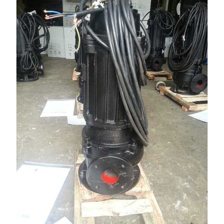
The XBD-L type single-suction multi-stage segmented fire pump consists of two parts: the motor and the pump. The motor is a Y-series three-phase asynchronous motor. The pump and motor are connected by a coupling, with a rigid overall connection that requires no alignment during operation. The pump is composed of the stator and rotor sections. The stator section is made up of the inlet section, middle section, guide vanes, outlet section, stuffing box, etc. To prevent stator wear, sealing rings and balancing sleeves are installed on the stator, which can be replaced with spare parts if worn. The rotor section can be composed of the shaft, impeller, balancing drum, etc. The lower end of the rotor features a water-lubricated bearing, while the upper end has angular contact ball bearings. The majority of the pump's axial force is borne by the balancing drum, with the remaining minor portion of the shaft downward force supported by the angular contact ball bearings. The joint surfaces of the inlet, middle, and outlet sections are sealed using paper gaskets that are tightened to achieve tightness, which the user can select as needed.
The pump rotates in a counterclockwise direction when viewed from the drive end.
The relationship between the fire hydrant control room and the operation of the fire hydrant buttons is related to the starting method of the fire hydrant pump. The starting methods of the fire hydrant pump generally fall into two categories. The first method involves using the bus system interlock mode, where the operation button of the fire hydrant can initiate its start signal through an interlock interface module located near the fire hydrant, which then sends the signal to the fire control room console. The console outputs switch points to start the fire hydrant. The second method directly outputs the switch points of the fire hydrant operation button to the fire hydrant pump start box. Both methods can be applied in actual design. The first method is more economical in wiring but requires addressing and programming the fire hydrant interlock module in the bus system for monitoring a large number of fire hydrants. The second method is simpler and more reliable, but it also requires returning the fire hydrant operation signal to the fire control room. Designers can choose the appropriate method based on the scale of the project; for larger projects with complex architectural forms, the first method is recommended, while the second method is suitable for smaller projects.
WeChat Official Account

Scan to follow Official Account