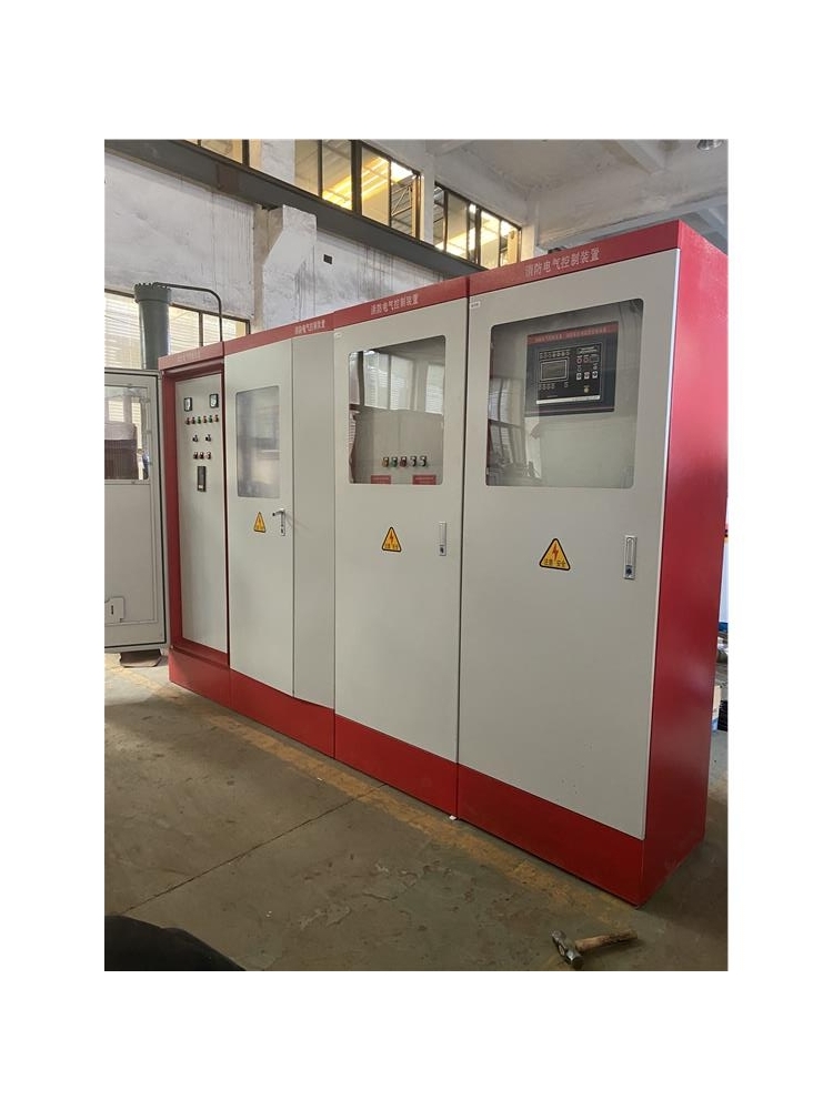


Electrical control cabinets feature traditional relays and PLC control. Simple controls are typically managed using relays, while complex controls usually employ PLC control. PLC stands for Programmable Logic Controller.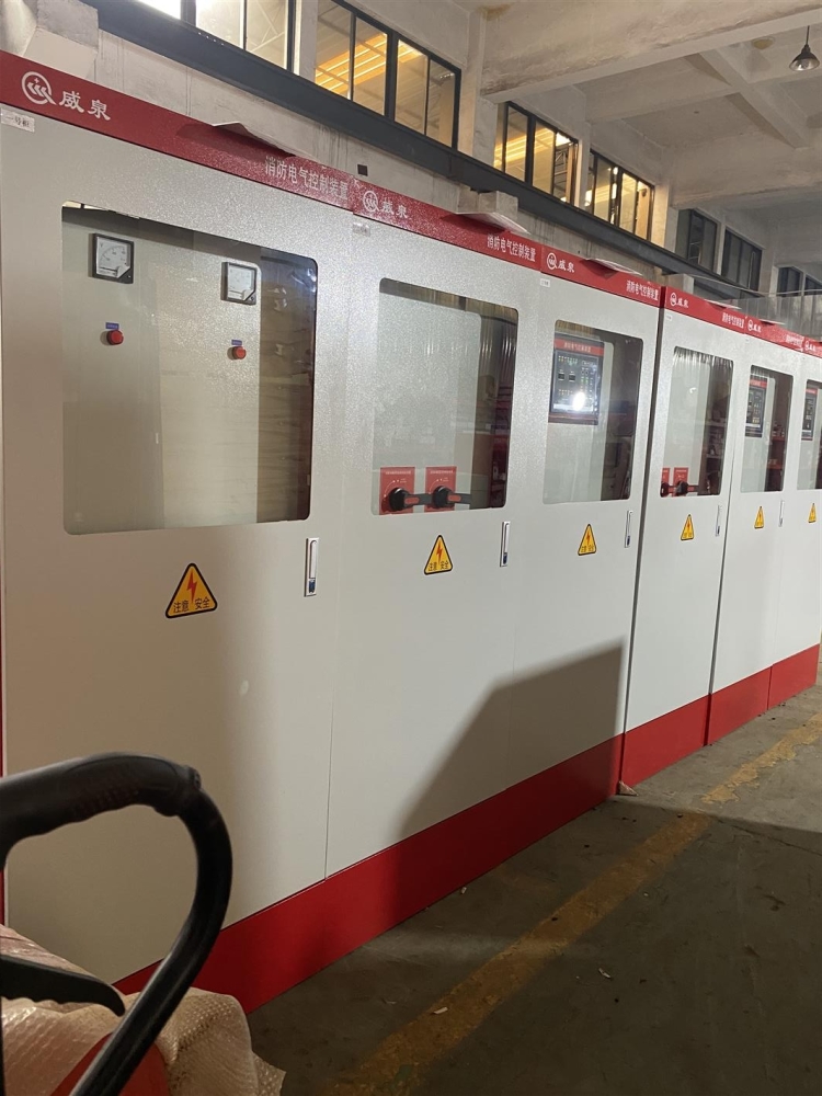
Feature Highlights: The programmable logic controller boasts the following distinctive features.
The system features flexible composition and easy expansion, excelling in switch quantity control; it also supports continuous process PID loop control; and can form complex control systems with higher-level units, such as DDC and DCS, to achieve comprehensive automation of the production process.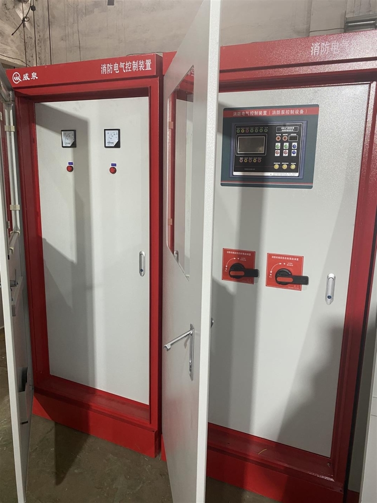
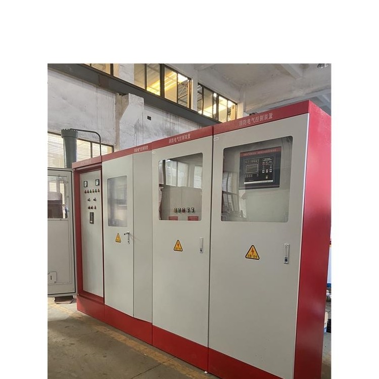
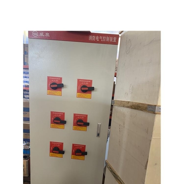
PLC control cabinets can achieve equipment and process automation control, featuring stable performance, scalability, and strong anti-interference capabilities, making them the core and soul of modern industry. They can be custom-designed according to user requirements, including PLC control cabinets and variable frequency cabinets, to meet specific needs and can be paired with human-machine interface touch screens for easy operation. The equipment can also communicate via data transmission protocols such as modbus, profibus on the DCS master station bus; and control is achieved through industrial computers, Ethernet, etc.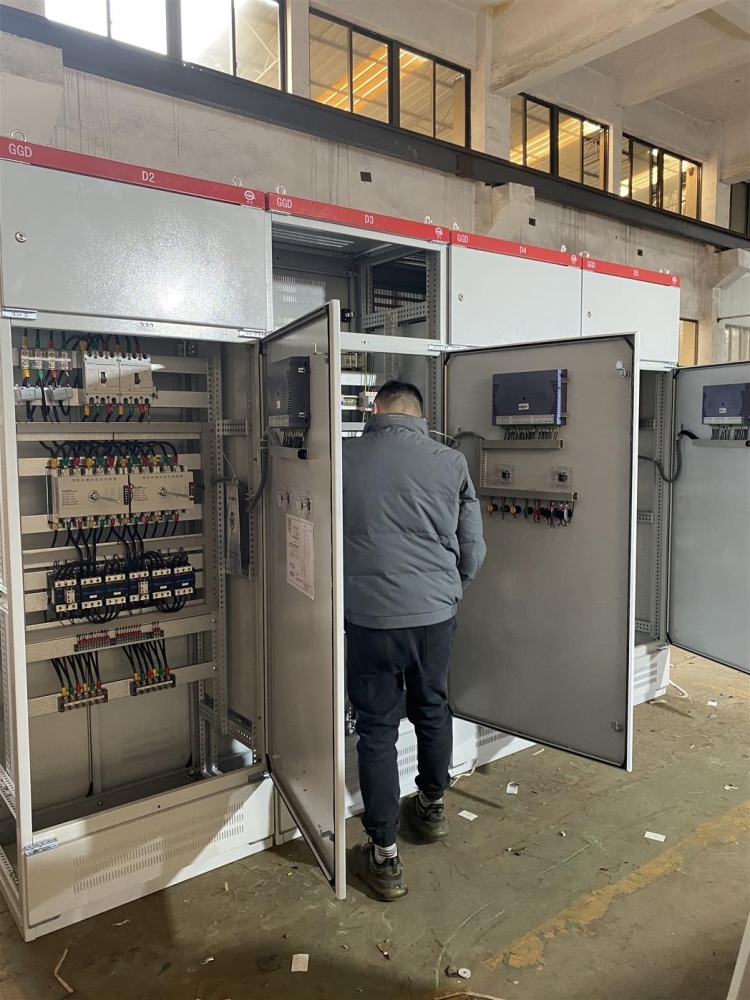
Communication Module
Operating Principle: Once the programmable logic controller is in operation, its process is generally divided into three stages: input sampling, user program execution, and output refresh. Completing these three stages constitutes one scan cycle. Throughout its operation, the CPU of the programmable logic controller repeatedly executes these three stages at a certain scan speed.
During the input scanning phase, the programmable logic controller sequentially reads all input states and data in a scanning manner and stores them in the corresponding units within the I/O image area. After the input scanning is completed, it transitions to the user program execution and output refresh phase. In these two phases, even if the input states and data change, the states and data of the corresponding units in the I/O image area will not be altered. Therefore, if the input is a pulse signal, the width of the pulse signal must be greater than one scan cycle to ensure that the input can be read under all circumstances.
During the user program execution phase, the programmable logic controller always sequentially scans the user program (ladder diagram) from top to bottom. When scanning each ladder diagram, it first scans the control circuit composed of various contacts on the left side of the ladder diagram, and performs logical operations on the control circuit in the order of left to right, and top to bottom. Then, based on the results of the logical operations, it refreshes the status of the corresponding bit in the system RAM storage area for the logic coil; or refreshes the status of the corresponding bit in the I/O mapping area for the output coil; or determines whether to execute the functional instruction specified by the ladder diagram. In other words, during the execution of the user program, only the status and data of the input points within the I/O mapping area remain unchanged, while the status and data of other output points and soft devices in the I/O mapping area or system RAM storage area may change. Moreover, the execution result of the ladder diagram that appears above affects the ladder diagrams below that use these coils or data. Conversely, the status or data of the logic coil refreshed in the ladder diagrams below can only affect the programs above during the next scan cycle. During program execution, if immediate I/O instructions are used, direct access to I/O points can be made. Even when using I/O instructions, the value of the input process image register is not updated, and the program directly fetches values from the I/O module. The output process image register is immediately updated, which is different from immediate inputs.
3. Upon completion of the scanning of the user program in the output refresh phase, the programmable logic controller enters the output refresh phase. During this period, the CPU refreshes all output latches by accessing the corresponding states and data in the I/O image area, and then drives the respective peripherals through the output circuit. This is when the actual output of the programmable logic controller occurs.
Function Features: The programmable logic controller boasts the following distinctive features.
1. The system is flexible in structure, easy to expand, with switching quantity control as its specialty; it also supports continuous process PID loop control; and can form complex control systems with higher-level units, such as DDC and DCS, to achieve comprehensive automation of the production process.
2. Easy to use with simple programming, featuring clear ladder diagrams, logic charts, or statement lists, no computer knowledge required. This results in a short system development cycle and easy on-site debugging. Additionally, programs can be modified online, changing control schemes without disassembling hardware.
3. Adaptable to various harsh operating environments, with strong anti-interference and reliability far exceeding other models.