


During the user program execution phase, the programmable logic controller (PLC) always sequentially scans the user program (ladder diagram) in an upward-to-downward order. When scanning each ladder diagram, it first scans the control circuit composed of the contacts on the left side of the ladder diagram, performing logical operations on the control circuit in the order of left-to-right, top-to-bottom. Then, it refreshes the state of the corresponding logical coil in the system RAM storage area based on the result of the logical operations; or refreshes the state of the corresponding output coil in the I/O image area; or determines whether to execute the function instruction specified by the ladder diagram. In other words, during the execution of the user program, only the states and data of the input points within the I/O image area remain unchanged, while the states and data of other output points and soft devices in the I/O image area or the system RAM storage area may change. The ladder diagram that appears first affects the ones below it that use these coils or data; conversely, the state or data of the logic coil refreshed in the ladder diagram below can only affect the program above it during the next scan cycle. If immediate I/O instructions are used during program execution, direct access to I/O points is possible. Even when using I/O instructions, the value of the input process image register is not updated; the program directly retrieves values from the I/O module, and the output process image register is immediately updated, which differs from immediate input.
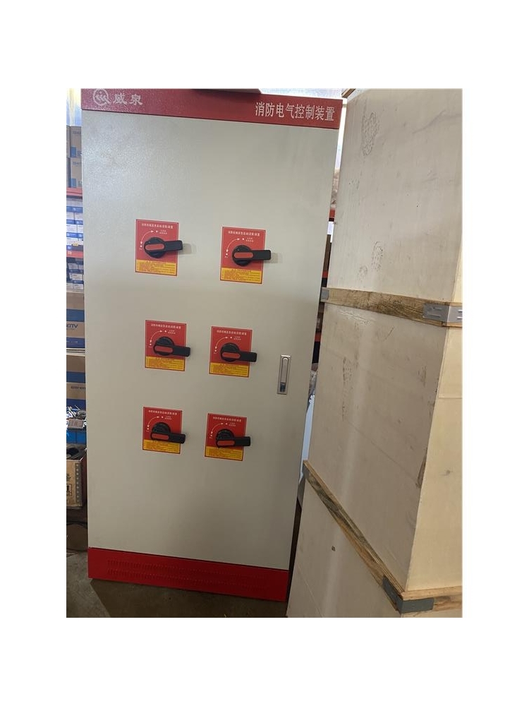
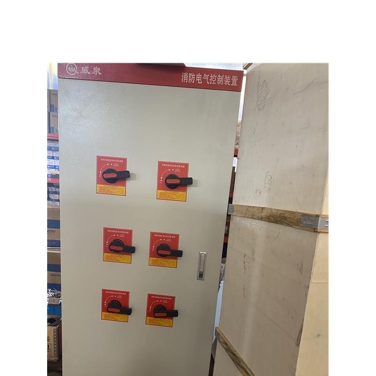
What's the issue with the fire control cabinet showing a main power failure?
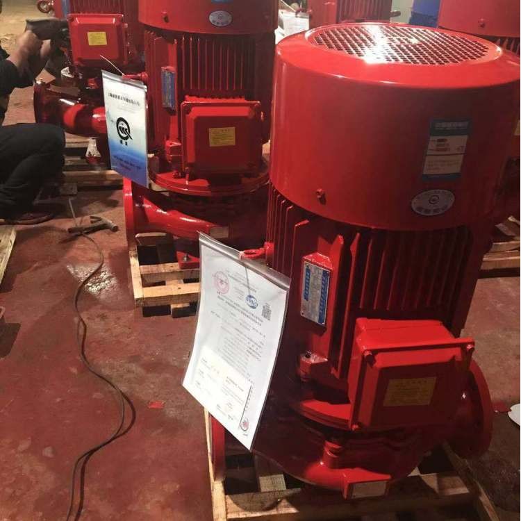
1. Fire protection electrical equipment is all supplied with dual-circuit power.
2. The fire control cabinet you're referring to is likely a fire alarm linkage controller.
3. The fire alarm linkage controller is powered by both municipal electricity and the controller's built-in float charge battery pack.
4. The controller is currently reporting a main power failure issue as follows:
(1) Power shortage.
(2) Main power fuse on the controller's power supply panel has blown.
(3) Controller power section malfunction.
Fire control cabinet maintenance methods
1. After you disconnect the main power to the control cabinet, carefully inspect each conversion switch. The start and stop button actions must be both flexible and reliable.
2. Thoroughly inspect the air switches, contactors, and relays within the cabinet to ensure they are intact and securely fastened to the contact terminals and wiring screws between the electrical components.
3. Electrical insulation testing of control cabinets, main and backup power supply switching, three-phase balance adjustment, and reinforced grounding connections.
4. Schedule regular checks and cleaning to remove dust from inside and outside the control cabinet.
5. When turning off the main power, ensure the power indicator is functioning correctly.
The above explains the functions, technical parameters, structural features, installation and operation, what the main power failure display on the fire control cabinet means, and maintenance methods by Weiquan Pump Industry. Of course, it is important to note that a thorough inspection must be conducted before powering on the fire control cabinet, checking for any short circuits or open circuits, as this condition is extremely dangerous. Additionally, when energizing, the control cabinet must be set to manual, which is a point to be aware of. During the use of the fire control cabinet, situations may arise where there is no water or inadequate ventilation. In such cases, a systematic check of the pump housing and piping is required to ensure they are fully filled with liquid. If they are, appropriate measures should be taken to address the issue. Furthermore, a low speed issue may occur, necessitating a check of the motor wiring and voltage to ensure they are correct and normal, as well as verifying the steam pressure of the turbine. When problems are identified, appropriate adjustments should be made.
The distribution panel mainly consists of switches, responsible for power distribution and circuit protection.
The control cabinet primarily performs control functions, typically containing switches, relays, or PLCs.
Wire Terminal
This is definitely a must-have for every container, configurable based on the number of signals. If it's just a plain PLC control cabinet, these items are typically required. If your control cabinet needs additional components, adjust accordingly. For instance, if you need to power certain on-site instruments or small control boxes, you might need to increase the number of circuit breakers. Or, if you need to connect the PLC to a higher-level computer, you may have to add switches and the like.