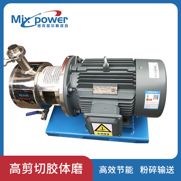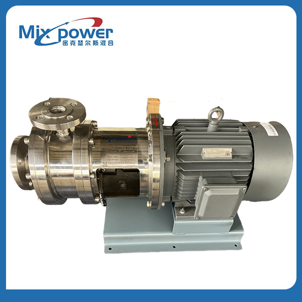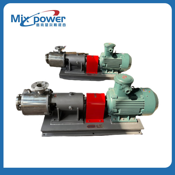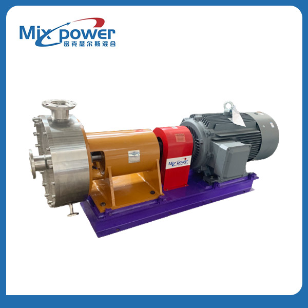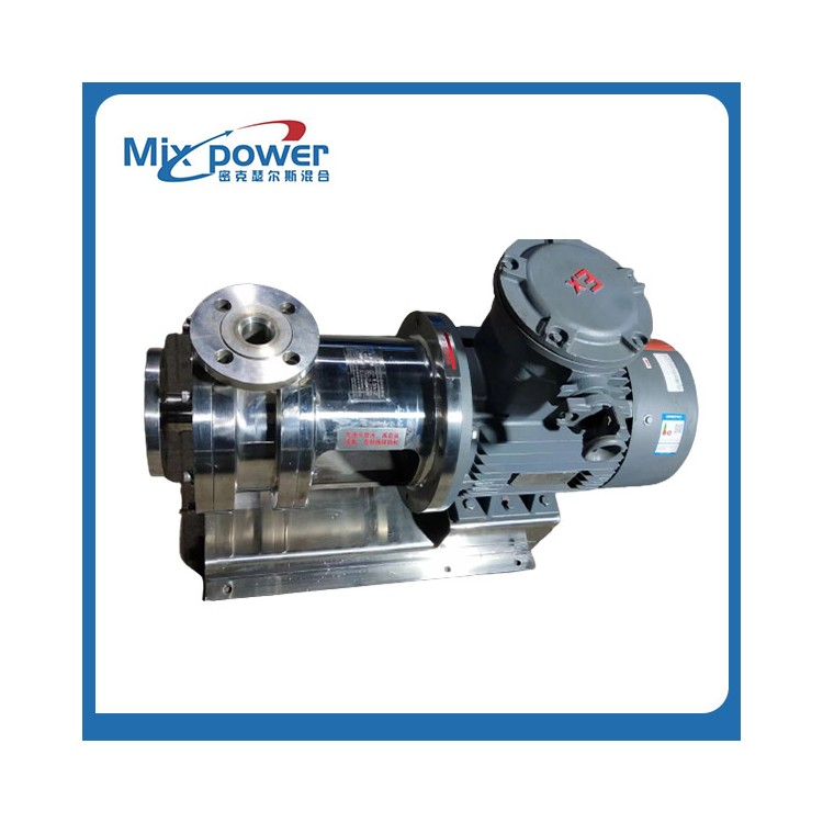


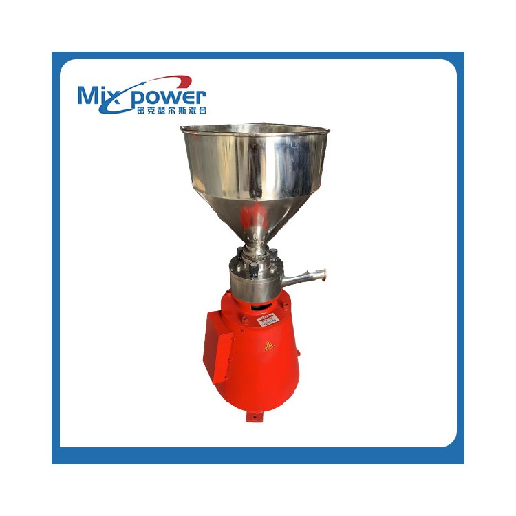
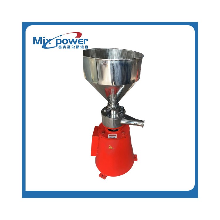
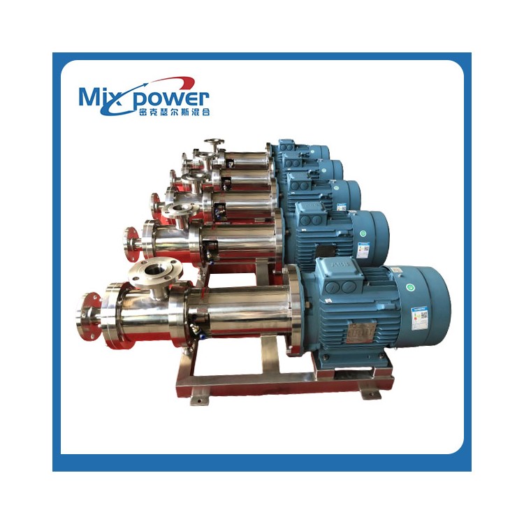


High-shear colloidal mill
Overview DEscriptION
A high-shear colloid mill is an energy-saving equipment that can wet shear, crush, and grind particles within pipelines, marking a new starting point in the wet grinding industry for particles both domestically and internationally. This equipment boasts advanced technology, multiple functions, energy-saving features, and particle crushing and conveying capabilities. Our company can also custom design and manufacture the equipment to cater to the specific characteristics of your material.
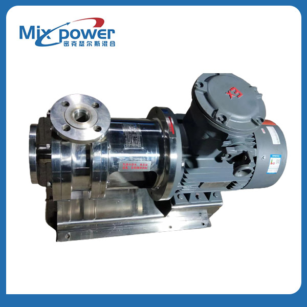
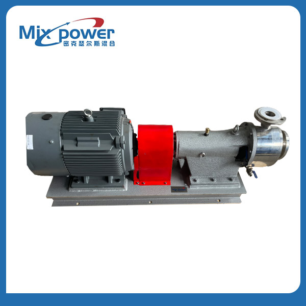
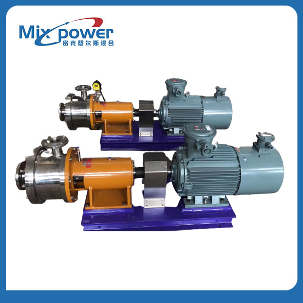
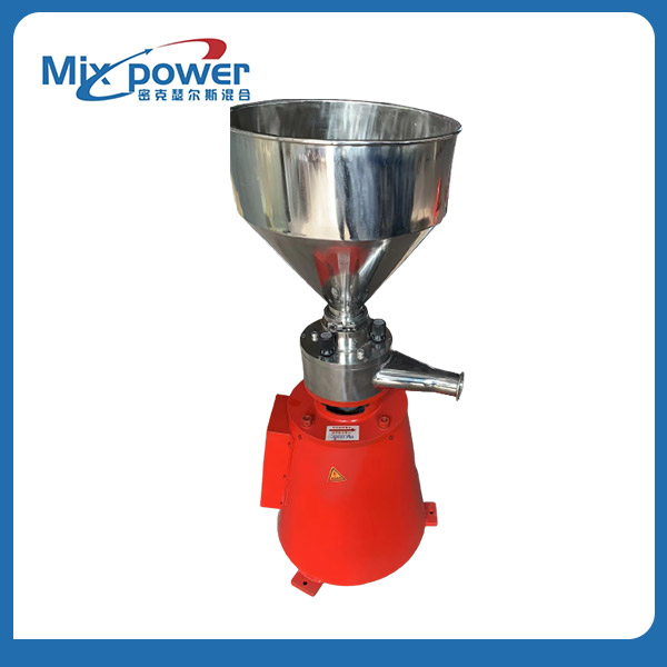
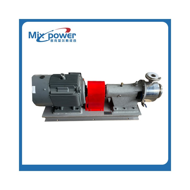
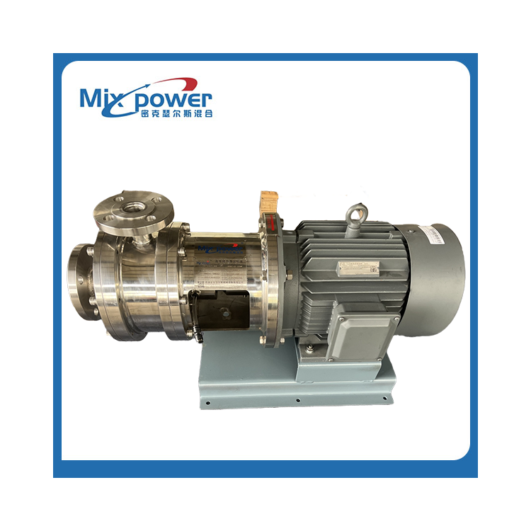
Main Structure
The high-shear colloid mill is designed and manufactured with a three-stage grinding area including a feeding shear zone, a crushing zone, a grinding zone, and a refining zone. The planar shear and crushing distance after the rotating stator is merged is generally 0.05mm (the adjustable distance between rotating stators is 0.01-2mm), with an outer diameter up to 600mm. The MAX high linear speed can reach 120m/s, and the ordinary conveying height can reach 3-6 meters, with the MAX height up to 50 meters.
Primary Features
High-shear colloid mills are mainly used for the crushing and grinding refinement of fragile particles such as crystals, lumps, agglomerates, sticky blocks, filter cakes, etc., present in pipeline fluids. They more energy-efficiently enhance the material reaction process and effectively ensure the flow capacity of subsequent pumps and valves. During the crushing and grinding process, the fluid must pass through a shear zone, a three-stage grinding zone, and then be extruded in a curved manner through a channel with approximately 0.3-0.6mm teeth after being dispersed and refined ten times. This creates a high-speed, high-pressure, and high-frequency atomization phenomenon, thereby significantly improving the particle crushing, dispersion, and emulsification capabilities.
Operating Principle FEATURE
Under the high-speed rotation of the motor, the material enters the high-shear crushing zone directly from the inlet, where it is rapidly broken down into smaller particles by a special crushing device, including large clumps, sticky lumps, and other aggregates. It is then drawn into the shearing crushing zone, where intense friction and grinding occur due to the high-speed cutting action of the rotor blades against the stator blades in a very narrow working channel. Under the action of mechanical motion and centrifugal force, the finely crushed material is re-pressed into the fine grinding zone for further grinding and crushing. The fine grinding zone is divided into three stages, with increasing blade precision, decreasing pitch, and longer linear velocity as it extends outward, resulting in finer material. Simultaneously, the fluid gradually extends in a curved radial direction. At each stage, the direction and speed of the fluid change instantaneously, subjected to millions of high-speed shearing, intense friction, compression grinding, and particle crushing per minute. After millions of high-speed shearing and grinding in three fine grinding zones, the liquid material achieves molecular chain breakage, particle crushing, and liquid-particle tearing, effectively dispersing, crushing, emulsifying, homogenizing, and refining the material. The minimum fineness of the liquid material can reach 0.5 micrometers, with a normal conveying height of 3-6 meters.
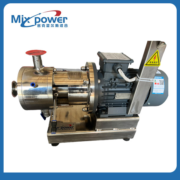
Job Characteristics
Robust crushing, dispersing, emulsifying, homogenizing, blending, and conveying functions
2. Silent design, noise-free, excellent dynamic balance, no vibration
3. Available materials for turning and grinding include 304, 316L, 2205, and 2Cr13, with options for nitriding or tungsten carbide treatment.
4. The gap is adjustable, with a range of 0.01~2mm.
5. Optional double-sided water-cooled mechanical seal or single-sided liquid-cooled mechanical seal
6. Continuous operation and intermittent work do not affect the lifespan of the equipment.
Performance Parameters
| Model | Processing Volume: m3/h | Motor Power: kW | Import/Export Dimensions mm | Contact Information |
| MX-JTM-G25 | 0.2~0.5 | 4 | 40/25 | Direct connection |
| MX-JTM-G32 | 0.5~2.5 | 7.5 | 50/32 | Direct connection |
| MX-JTM-G40 | 2~4.5 | 11 | 50/40 | Direct connection |
| MX-JTM-G50 | 3~7 | 18 | 65/50 | Bearings Mounting Connection |
| MX-JTM-G65 | 5~12 | 30 | 80/65 | Bearings Mounting Assembly |
| MX-JTM-G80 | 9~18 | 37 | 100/80 | Bearing housing connection |
| MX-JTM-G100 | 14~34 | 45 | 125/100 | Bearing Mount Connection |
| MX-JTM-G125 | 24~44 | 55 | 150/125 | Bearing housing connection |
| MX-JTM-G150 | 30~60 | 75 | 175/150 | Bearing Mount Connection |
| MX-JTM-G175 | 40~80 | 95 | 200/175 | Bearing housing connection |
Note:
Motor power is configured according to the material's viscosity and particle hardness.
2. The internal structure varies according to the particle size and viscosity of the material, with a new non-standard structure code added after the product model.
3. Equipment installation bases without bearing seats are generally 1200.600mm, equipment with bearing housing 1800600mm size. Like JTM-G80.