


I. Product Overview:
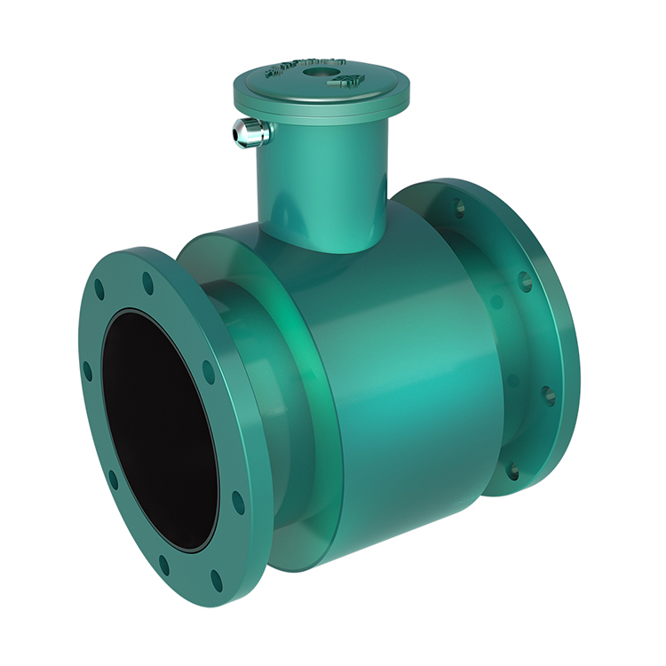
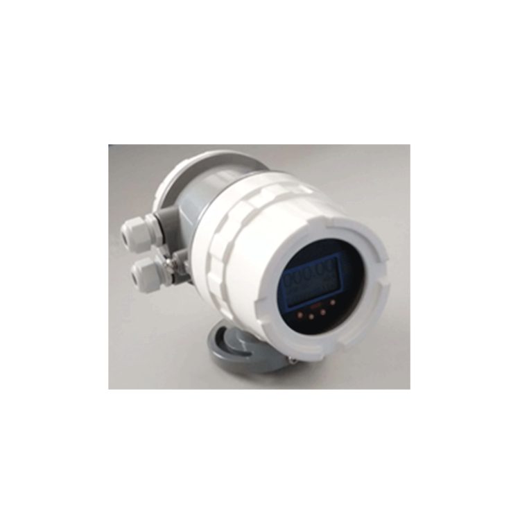
The MGG/KL-CC Insertion Type Electromagnetic Flow Meter is a combination of an insertion electromagnetic flow sensor and a converter, designed to measure the volume flow of various conductive liquids within pipelines. The MGG/KL-CC Insertion Type Electromagnetic Flow Meter is widely used for measuring conductive fluid flow in municipal water supply and drainage, steel, petroleum, chemical, power, industrial, and hydraulic departments, and can also be used for measuring corrosive conductive liquids such as acids, alkalis, and salts.
Section II: Product Features:
Simple, sturdy, no moving parts, and long service life
Reliable measurement, strong anti-interference capability
Compact, lightweight, easy to install, and low maintenance requirements
Wide measurement range;不受温度、密度、压力、粘度、电导率等变化的影响
Pressure loss is zero
Can be installed and dismantled without interruption of water supply, suitable for applications where water supply cannot be shut off or for the renovation of old pipelines.
Lower cost and installation fees compared to general electromagnetic flow meters, especially suitable for measuring flow in medium and large diameter pipes.
Processed with advanced technology, featuring solid packaging, vibration resistance, and long service life, the instrument offers excellent measurement accuracy and stability.
Flow meters not only feature standard current outputs of 0-10mA or 4-20mA, but also provide frequency outputs ranging from 1-5000Hz.
Digital Communication Outputs: RS232, RS485, HART
Section 3: Technical Specifications:
Flow Rate Measurement Range: 0 m/s - 15 m/s
Pipe Diameter Measurement: DN32mm - DN3000mm
Measurement Accuracy: 1.0 Grade
Working Pressure: ≤1.6 MPa
Medium Temperature: 0℃—80℃
Power Consumption: <20W
Protection Rating: IP68
Connection Methods: Flange Connection, Threaded Connection
Supply Voltage: 220VAC, 24VDC/12VDC, and supports automatic switching between 3.6VDC/12VDC and 220VAC multi-voltage power supply.
Four: Installation Method
Selection of Installation Environment
Keep a safe distance from equipment with strong fields, such as large motors and transformers.
Installation location should not experience severe vibrations; pipes must be securely fastened. The environmental temperature should fluctuate minimally.
The installation environment should be convenient for installation and maintenance.
Selection of Installation Location
The installation location must ensure that the pipeline is always filled with the fluid being tested.
Choose a location with minimal fluid flow pulsation, which should be far from pumps, valves, elbows, and other local resistance components.
When measuring biphasic (solid/liquid or gas/liquid) fluids, select locations where phase separation is unlikely to occur.
Avoid creating a vacuum at the measurement location.
The diameter or circumference of the side pipe is easily measurable, and the ellipticity should be minimal.
Straight Pipe Length
The straight pipe section length upstream of the sensor installation should be greater than or equal to 10D, and downstream should be no less than 5D (where D is the diameter of the pipe being measured).
Flow Control Valves and Regulating Valves
The flow control valve should be installed on the upstream side of the pipe from the sensor, while the flow regulating valve should be installed on the downstream side. During measurement, the flow control valve should typically be in the fully open position.
Section 5: Installation Method
Vertical installation; the sensor should be inserted perpendicular to the pipeline's central axis, with an angle less than 50 degrees to the pipeline cross-section, suitable for measuring minor pipeline vibrations in clean media.
There are two methods for inserting the electromagnetic flow sensor insertion point: one is at 1/4 of the pipe inner diameter, and the other is at 1/2 of the pipe inner diameter.
Properly weld the mounting base to the pipe, and clean off the weld slag and burrs from the installed pipe base.
Shut off the upstream flow control valve or use low-pressure water supply.
Install the DN50 ball valve onto the mounting base. Ensure the long cavity of the ball valve is facing upwards. Check if the ball valve can be fully opened and closed. If there are issues, perform repairs. Attach the tightening sleeve, nut, and rubber sealing ring to the ball valve. Loosen the positioning bolt and nut, then insert the sensor into the pipe through the ball valve. Tighten the nut and bolt, while also ensuring the sensor's directional mark is aligned with the fluid flow direction.
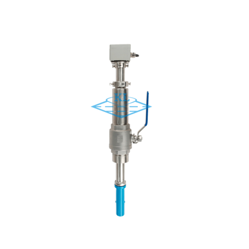
V. Installation Site Photos of Insertion Type Electromagnetic Flow Meters
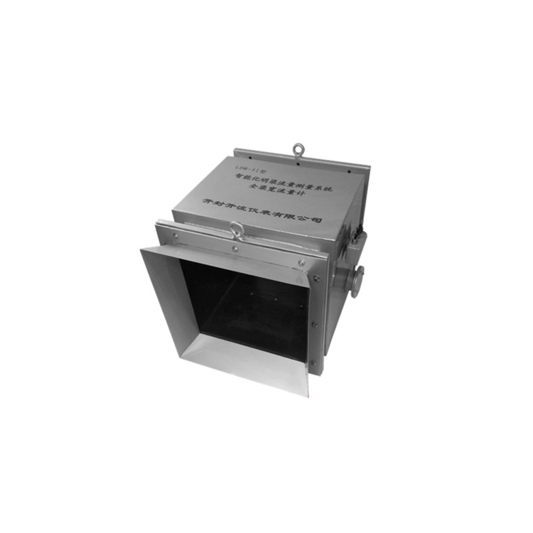
Open Flow Meters
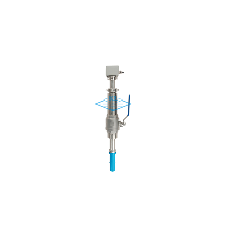
Flowmeter
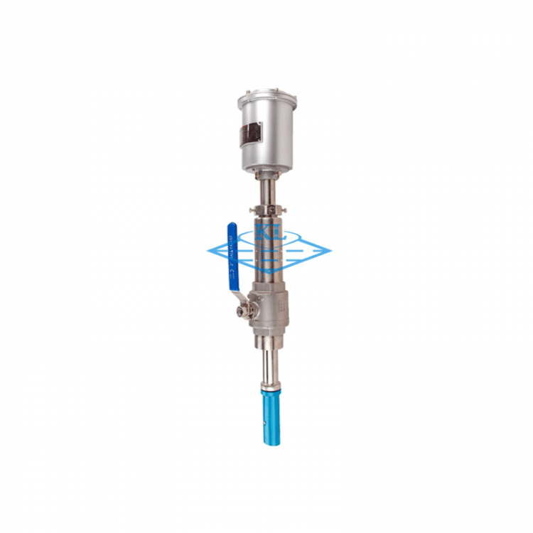
Flowmeter
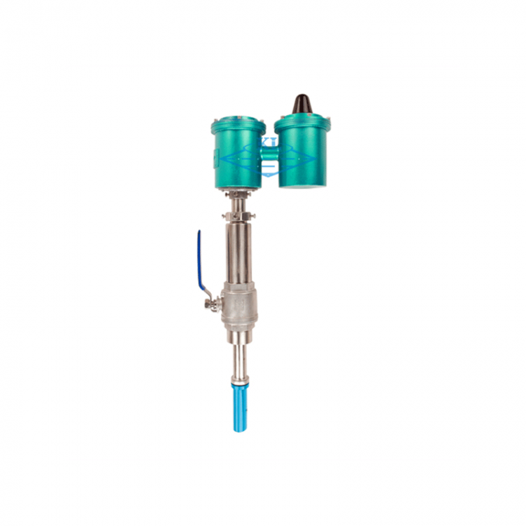
Flowmeter
Fujian Yingtan Sanchuan Pump Co., Ltd. Flanged Ball Valve Insert Type Electromagnetic Flowmeter