


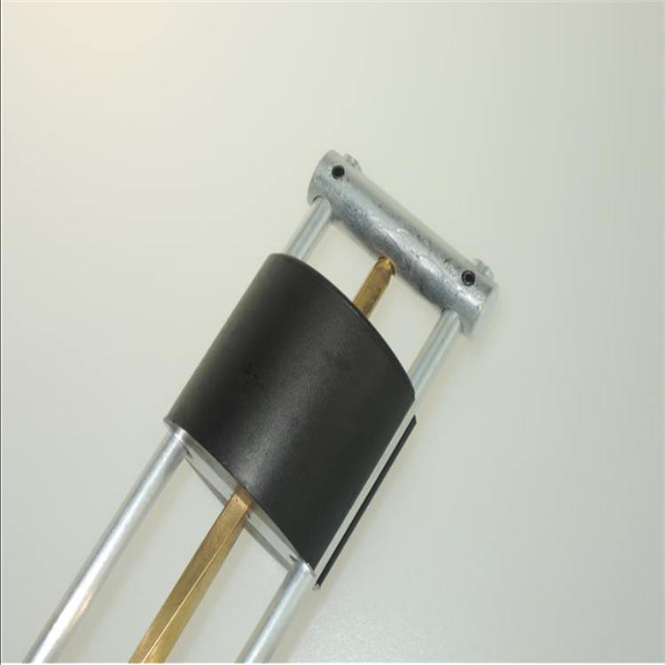
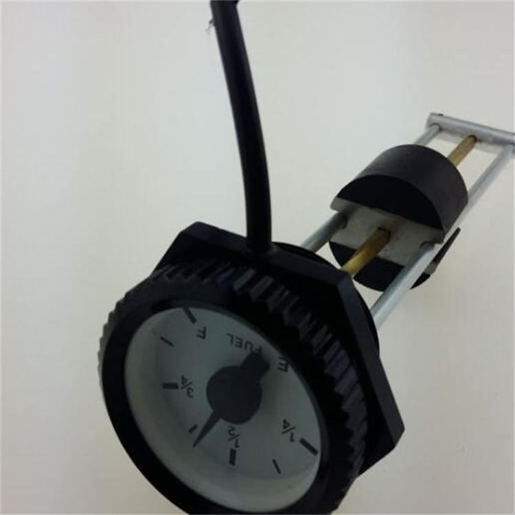
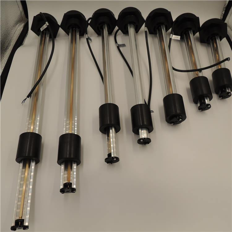
A mechanical oil gauge is a high-precision volumetric flow meter that displays the instantaneous and cumulative flow of diesel. The cumulative flow can be reset and can be used in conjunction with a PLC quantitative control system for precise control. This flow meter offers more stable performance and accuracy than standard electronic flow meters, with a longer service life. Properly installed according to specifications, the diesel flow meter ensures sufficient accuracy during use, with the cumulative value typically achieving a 0.5 level of precision, making it a relatively accurate flow measurement instrument.
Installation Environment Requirements for Mechanical Oil Gauges:
1. Opt for locations with minimal dust, no corrosive gases, minimal vibration, and a considerable distance from heat sources whenever possible.
2. The flow meter should be installed in an environment with a temperature of -15 to 40°C.
Mechanical oil gauges are divided into vibration-resistant oil pressure gauges and anti-vibration oil pressure gauges. The vibration-resistant oil pressure gauge is filled with high-viscosity mineral silicon oil in the spiral spring tube and housing, which serves as a damping effect. It can reduce the vibration and increase the resistance to vibration of the pointer, thereby minimizing pointer oscillation. The mechanical oil gauge integrates level detection and display in one unit, eliminating the need for external equipment. It can directly display level output signals. Optional, it can output 9 resistance signals, customizable resistance ranges according to customer requirements. High and low level alarm functions can be added upon customer request.
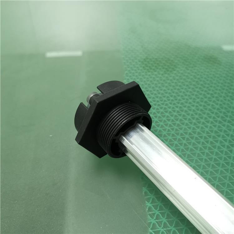
Technical requirements for mechanical oil gauge installation:
1. The elliptical gear flow meter has no specific requirements for the upstream and downstream straight pipe sections. It can be installed horizontally or vertically. During installation, the rotation axis of the elliptical gears of the flow meter should be parallel to the ground.
2. During on-site installation, pay attention to the arrow direction on the flowmeter housing and the flow direction of the fluid.
3. The tested fluid should not contain particles or impurities; otherwise, a filter must be installed before the flow meter's inlet. If the fluid contains a large amount of debris, the filter diameter should be one size larger than the standard or a parallel double filter should be installed. If gas is present, an exhaust device should be installed.
4. The fluid being tested should fill the flowmeter's measuring chamber and its connecting pipes before and after. If the fluid contains gas, a gas separator should be installed before the flowmeter and filter.
5. Flow meters should be installed on pipes with nominal inner diameters matching their inlet and outlet connections. When connecting the pipe to the flow meter, the sealing components should not protrude into the fluid.
6. For continuous operating pipelines, a bypass pipeline should be installed when the flowmeter is mounted on a horizontal pipe to facilitate cleaning and maintenance; when the flowmeter is mounted on a vertical pipe, it should be installed in the bypass pipeline to prevent debris from falling into the instrument. When the fluid flows from bottom to top, the vertical pipe above the flowmeter should be as short as possible to minimize sedimentation of impurities in the upper piping.
WeChat Official Account

Scan to follow Official Account