


I. Introduction
Megohmmeter Calibration Instrument | Megohmmeter Verification Device | Insulation Resistance Meter Verification Device
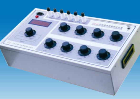
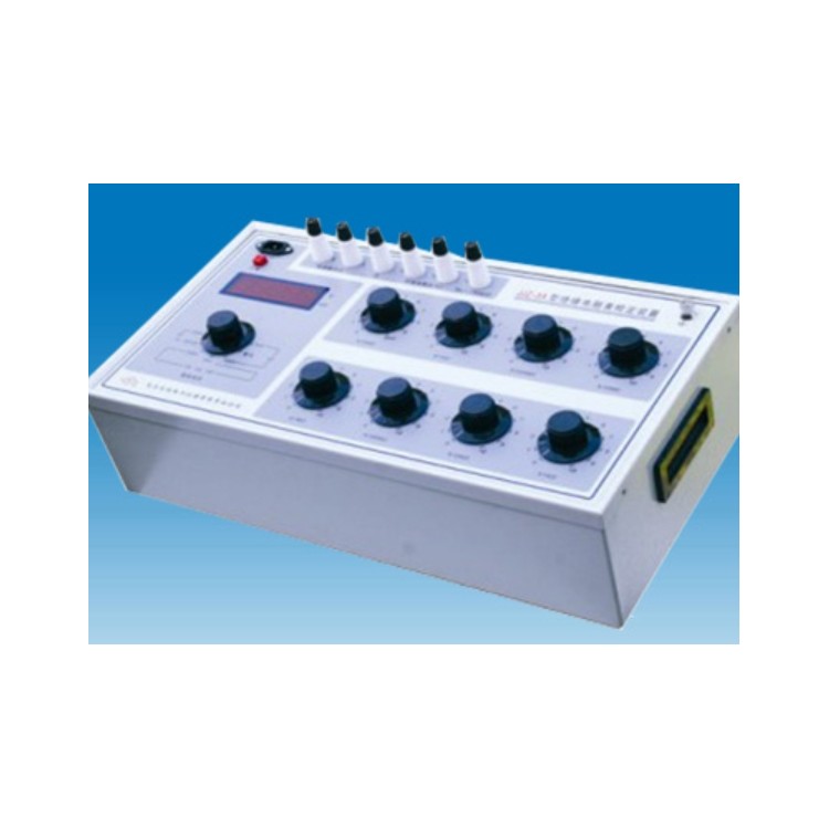
The HGZX5KV Type Insulation Resistance Meter Calibration Device (Megohmmeter Calibration Device) is a specialized equipment designed and manufactured in accordance with the requirements of the JJG1005—2005 "Electrical Insulation Resistance Meter Verification Regulations" and the JJG622—1997 "Insulation Resistance Meter (Megohmmeter) Verification Regulations," and with reference to the relevant content of the general technical conditions for electrical insulation resistance meters in the power industry standard DL/T845.1—2004. It is used for verifying the indication error, voltage drop, and short-circuit current of electronic insulation resistance meters. When paired with our company's constant-speed drive (CY3 model), it can also verify the indication error, open-circuit voltage, mid-value voltage, and peak voltage of pointer-type megohmmeters. It features a compact structure, stable performance, and ease of use. It is an ideal device for various industrial and mining enterprises, as well as institutions, to verify all types of insulation resistance meters.
II. Main Technical Specifications
HGZX5KV Insulation Resistance Meters Calibration Device (Megger Calibration Device) is primarily used for calibrating various insulation resistance meters with rated voltage ≤ 5000V, and can also serve as a standard instrument during the production and repair of insulation resistance meters. The resistor section can be used independently. The digital meter section can measure up to 5000V DC voltage and up to 20mA DC current.
The main technical specifications of this calibration device are as follows:
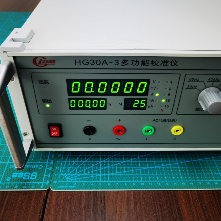
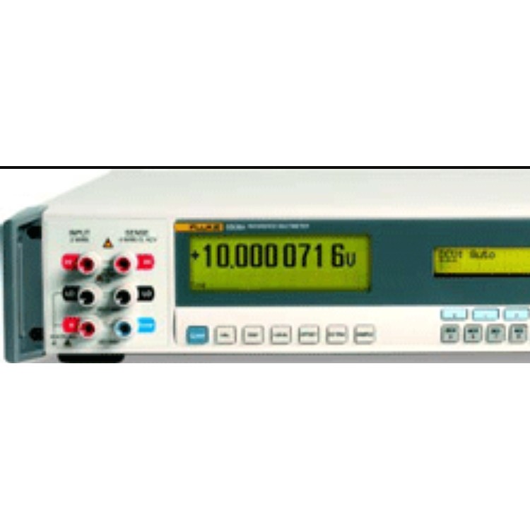
Standard Digital Gauge
1. Measuring Range:
Voltage divided into two levels: 0-500V, 0-5000V
Short-circuit Current: 0~2mA / 0~20mA
2. Basic Tolerance:
Direct Current Voltage | ≤500V: ±(0.4% of reading + 0.1% of full scale) >500V: ±(0.5% of reading + 0.5% of full scale) |
Peak Voltage | ≤500V: ±(1% of reading + 0.5% of full scale) > 500V: ± (0.5% of reading + 0.5% of full scale) |
Short-circuit current | ±(0.3% of reading + 0.2% of full scale) |
3. The response time of the digital gauge is approximately 25 seconds.
㈡ Standard ResistorEquipment
1、Standard ResistorDevice with a 100G fixedResistorWith eightResistorDisk assembly
100GΩ+9×10⁴ MΩ+10×(103+102+10+1+0.1+0.01
+0.001)MΩ,
0 to 201111.110 MΩ, 1KΩ step, high voltage resistance 5KV.
2. Grade index and peak voltage or current for each decade disk
3. ResidualResistorValue less than 1Ω, tolerance not exceeding 0.1Ω.
4. Environmental reference conditions: 20+2-3°C, relative humidity: 50% ± 10%.
5. Nominal Operating Environment: Temperature 23±5°C, Relative Humidity: 25% to 60%.
6. Insulation of the circuit to the housingResistor≥1×10^11 Ω. 8KV test for one minute.
8. Power Voltage: AC 220V, 50Hz.
9. Dimensions: 530mm x 250mm x 170mm.
Weight: Approximately 17kg.
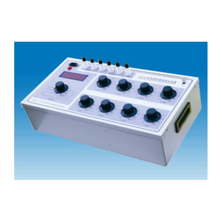
Section 3: Panel Settings and Instructions
This calibration device consists of a standard digital meter andStandard ResistorIt consists of two parts.
1. Standard digital meters can be used to measure voltage and current, positioned on the left side of the equipment.
The edges are designed for ease of use, with the voltage and current input terminals set separately. The central left side features an LED display with a larger screen size for increased visibility. The digital meter's measurement selection switch is located in the lower left corner, allowing you to choose different test items and measurements as needed.Range。
Panel Character Descriptions: Uk— Open Circuit Voltage Uf— Peak Voltage
UZ— Mid-Value Voltage Ud— Drop Voltage
Id— Short Circuit Current
2、Standard ResistorPlease provide the Chinese content to be translated.ResistorA design and manufactured based on series-parallel principles, output is altered by rotating a decimal disk switch.ResistorValue.ResistorThe device consists of two terminals and eight switches.
OK, two terminal posts betweenResistorThe value is derived by summing the readings from each indicator disk.
Four: Usage Instructions
1. Insulation verificationResistorThe indication (basic) error of the gauge should be connected according to the method shown in Figure 2, then connect the electronic insulation.ResistorWatch's power source activates the constant-speed drive to rotate the pointer insulationResistorTables, inspected point by point according to the procedures and requirements of the calibration methodResistorVerification of the indicator error and tilt influence of the clock.
2. Insulation VerificationResistorThe table shows the peak voltage of the open-circuit voltage and the short-circuit current wiring as in Figure 3. Simply set the "Measurement Selection" switch of this device to the corresponding position to start the test.
3. Insulation VerificationResistorWiring diagram for the median (dropout) voltage of the table is shown in Figure 4. Refer to Appendices 2 and 3 to determine the tested table.Mid-value resistorValue, the device of this typeStandard ResistorAdjust the resistor to the desired value, then place the "Measurement Selection" switch in the appropriate position for testing.
V. Usage Precautions
1. When using this calibration device, the environment should meet the aforementioned requirements. The instrument must have a good grounding wire.
2. When the calibration device has not been used for an extended period, it should be...Standard ResistorTurn the switches on the equipment several times between 0 and 10 (9) to ensure stable and reliable contact.
3. When in use, pay attention to the actual force applied toStandard ResistorThe voltage on the device should not exceed each respective limit.ResistorPeak voltage usage of the plate, to avoidResistorComponents are oversized or even damaged.
4. Due to the longer time constant (approximately 25S) of the digital voltmeter, the speed controller must be stopped or the power to the electronic insulation meter turned off after a single measurement is completed.RangeSelect "About Discharge" location, wait until the high voltage drops below 100 volts before changing.RangeOr modify the measurement items to ensure the safety of the testers and equipment.
5. During the measurement process, if the voltmeter flickers between bright and dim, it indicates that the input voltage is too high orRangeIncorrect, or the switch position is not placed correctly, needs to be switched to the correct position.Range。
6. During peak voltage measurement of this product, zero-point compensation is used to overcome peak sampling.
Forward voltage drop of the rectifier in the circuit. Therefore, even without an input signal, there is a certain size for the Uf range.
7. The insulation strength between the line and the casing should be capable of withstanding a 50Hz sine wave voltage.
Appendix 1
Megohmmeter Model | Median resistance value |
ZC25-3 (Old 5050 Model) | 10MΩ |
ZC11D—8 | 2MΩ |
ZC11—8 | 2MΩ |
ZC25-4 (Old 1010 model) | 20MΩ |
ZC11D—3 | 20MΩ |
ZC11D—5 | 100MΩ |
ZC11D—10 | 50MΩ |
ZC11—10 | 50MΩ |
ZC11—5 | 100MΩ |
The zero composition is a normal phenomenon.
Special Note: When calibrating the standard digital gauge of this device, please ensure that the signal from the standard source is returned to zero as per routine before turning the gauge.RangeSelect "switch" to avoid accidental damage to the standard source.
Article VI
1. Randomly supplied documents and attachments:
Packing List One copy
(2) Instructions Manual - One copy
(3) Product Compliance Certificate - One Copy
(4) Test Line A Pair
(5) Power Cord - One piece
2. Under the condition that users adhere to the storage and usage regulations, if the product fails to operate normally due to poor quality within 12 months from the date of shipment from the factory, our factory will repair the product for the user at no cost.
Appendix 2
JJG1005—2005 "Electrical Insulation"ResistorTable》RegardingMedian ResistanceWith fallResistorSelection requirements:
1. The pointer-style meter measures the allowable mean voltage for the terminal.
The pointer on the analog meter should be close to the scale line with marked values that is near the geometric center. The voltage between measurement terminals L and E is the mid-value voltage, which should not be less than 90% of the rated voltage. The central scale of the analog meter.ResistorThe value is generallyRange2% to 2.5% of the upper limit.
1. Allowable drop voltage for digital meters
Digital gauge displays the value provided by the manufacturer for drop testResistorAt value, the voltage measured between terminals L and E is the drop voltage.
The value should not be less than 90% of the rated voltage. The digital meter's dropResistorThe value should be within 1% of the upper limit of the basic quantity.