


I. Introduction
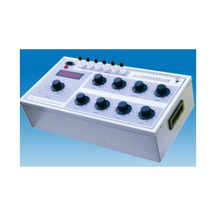
HGZX5KV Megger Calibration Device | Megger Calibration Instrument | Megger Calibration Device | InsulationResistorCalibration Table Device
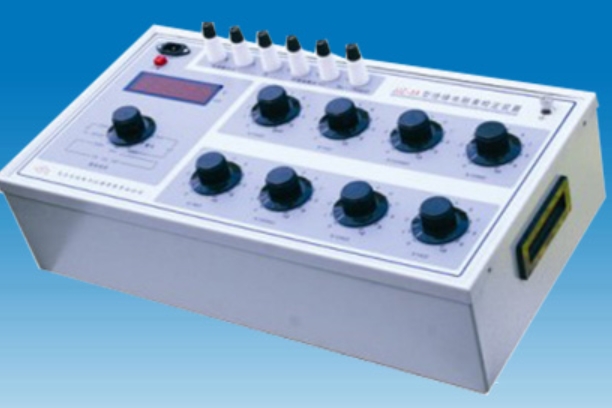
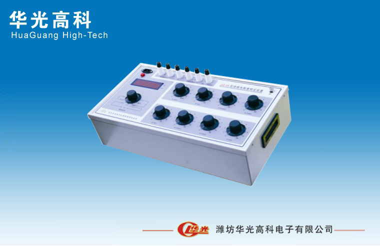
HGZX5KV Type Megohmmeter Calibration DeviceIs based on JJG1005—2005 "Electrical Insulation"ResistorTable Inspection Procedure, JJG622-1997 InsulationResistorRegulations for calibration of megohmmeters, and refer to the power industry standard DL/T845.1—2004 "Electrical Insulation Resistance Meters."ResistorSpecial equipment designed and manufactured in accordance with the relevant contents of the General Technical Conditions for Inspection and Calibration of Electronic InsulationResistorIndication error of the meter, drop voltage, short-circuit current. When paired with our company's constant speed drive (CY3 model), it can be used to calibrate the indication error, open-circuit voltage, mid-value voltage, and peak voltage of pointer-type megohmmeters. It features a compact structure, stable performance, and ease of use. It is used by various industrial and mining enterprises, as well as institutions, for calibrating all types of insulation.ResistorIdeal equipment for watches.
II. Main Technical Specifications
HG-Z Type InsulationResistorTable calibration device (Megger calibration device) mainly used for the calibration of various insulating materials with rated voltage ≤ 5000VResistorTables, also available in insulatedResistorTable for standard instruments in production and repair.ResistorThe instrument section can be used independently. The digital meter section can measure up to 5000V DC voltage and a higher 20mA DC current.
The main technical specifications of this calibration device are as follows:
Standard Digital Gauge
1. Measurement Range:
Voltage divided into two levels: 0-500V, 0-5000V
Short-circuit Current: 0~2mA, 0~20mA
2. Basic Tolerance:
Direct Current Voltage | ≤500V: ±(0.4% of reading + 0.1% of full scale) > 500V: ±(0.5% of reading + 0.5% of full scale) |
Peak Voltage | ≤500V: ±(1% of reading + 0.5% of full scale) >500V: ±(0.5% of reading + 0.5% of full scale) |
Short-circuit current | ± (0.3% of reading + 0.2% of full scale) |
3. The digital gauge's response time is approximately 25 seconds.
㈡ Standard ResistorVessel
1、Standard ResistorDevice with a 100G fixedResistorWith eightResistorDisk assembly
100GΩ+9×10⁴ MΩ+10×(103+102+10+1+0.1+0.01
+0.001)MΩ,
0 to 201111.110 MΩ, with a small step of 1KΩ, and high voltage resistance of 5KV.
2. Grade indices for various 10-pole disks and high operating voltages or currents
3. ResidualResistorValue less than 1Ω, tolerance not exceeding 0.1Ω.
4. Environmental Reference Conditions: 20+2-3°C, Relative Humidity: 50% ± 10%.
5. Nominal operating conditions: Temperature 23±5°C, relative humidity 25% to 60%.
6. Insulation of the wire from the housingResistor≥1×10^11 Ω. 8KV test per minute.
8. Power Voltage: AC 220V, 50Hz.
9. Dimensions: 530mm x 250mm x 170mm.
Weight: Approximately 17 kg.
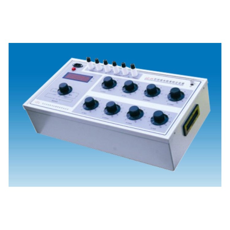
Section 3: Panel Settings and Instructions
This calibration device consists of a standard digital meter andStandard ResistorTwo parts make up the product.
1. Standard digital meters are used to measure voltage and current, positioned on the left of the device.
Edges are conveniently designed with separate voltage and current input terminals. The LED display, positioned in the middle of the left side, boasts a larger display size for increased visibility. The digital meter's measurement selection switch is located in the lower left corner, allowing the selection of different test items and measurement options as needed.Range。
Panel character descriptions: Uk— Open Circuit Voltage Uf— Peak Voltage
UZ— Mid-Value Voltage Ud— Drop Voltage
Id - Short Circuit Current
2、Standard ResistorPlease provide the Chinese content to be translated.ResistorSeries-parallel principle design and manufactured, output altered by rotating the decimal dial switchResistorValue.ResistorTwo terminals and eight switches make up the device.
OK, two terminal posts betweenResistorThe value is obtained by adding the readings from each indicator disk.
IV. Instructions for Use
1. Insulation CalibrationResistorThe indicating (basic) error of the gauge should be connected according to the method shown in Figure 2, and then the electronic insulation should be connected.ResistorWristwatch power supply, starts constant-speed motor to rotate pointer, insulatedResistorTables, inspecting insulation point by point according to the method and requirements of the calibration regulationsResistorVerification of indicator error and tilt influence on the watch.
2. Insulation CalibrationResistorThe table shows the peak voltage of the open-circuit voltage and the short-circuit current wiring as in Figure 3. Simply set the "Measurement Selection" switch to the appropriate position to power on and test the device.
3. Insulation VerificationResistorThe wiring diagram for the median (dropout) voltage of the table is shown in Figure 4. Refer to Appendices 2 and 3 to determine the tested table.Median ResistanceValue, the device of this typeStandard ResistorAdjust the resistor to the desired value, then place the "Measurement Selection" switch in the appropriate position for testing.
V. Usage Precautions
1. When in use, this calibration device requires an environment that meets the aforementioned requirements. The instrument must have a good grounding wire.
2. When the calibration device has not been used for a prolonged period, it should be...Standard ResistorTurn the switches on the equipment several times between 0 and 10 (9) to ensure stable and reliable contact.
3. When in use, attention should be paid to the actual force being appliedStandard ResistorThe voltage on the device should not exceed eachResistorPeak voltage usage of the disk, to avoidResistorComponents are oversized or even damaged.
4. Due to the longer time constant of the digital voltmeter (approximately 25 seconds), it is necessary to stop the constant-speed motor or turn off the power to the electronic insulation meter after one measurement is completed.RangeSelect "Location of discharge" option, wait until the high voltage drops below 100 volts, then switchRangeOr alter the measurement items to ensure the safety of the testers and equipment.
5. During the measurement process, if the voltmeter flickers between bright and dim, it indicates that the input voltage is too high orRangeIncorrect, or the switch position is not placed correctly, needs to be switched to the correct position.Range。
6. During peak voltage measurement of this product, zero-point compensation is employed to overcome peak sampling.
Forward voltage drop of the rectifier in the circuit. Therefore, even without an input signal, there is still a certain size for the Uf tap.
7. The insulation strength of the circuit to the shell should withstand a 50Hz sine wave voltage.
Appendix 1
Megohmmeter Model | Median resistance value |
ZC25-3 (Old 5050 Model) | 10MΩ |
ZC11D—8 | 2MΩ |
ZC11—8 | 2MΩ |
ZC25-4 (old 1010 model) | 20MΩ |
ZC11D—3 | 20MΩ |
ZC11D—5 | 100MΩ |
ZC11D—10 | 50MΩ |
ZC11—10 | 50MΩ |
ZC11—5 | 100MΩ |
The zero position of the switch is a normal phenomenon.
Special Note: When calibrating the standard digital gauge of this device, be sure to first return the signal of the standard source to zero before turningRangeSelect "switch" to avoid accidental damage to the standard source.
Article VI
1. Randomly supplied documents and attachments:
Packing List - One Copy
(2) Instruction Manual – One copy
(3) Product Compliance Certificate - One Copy
(4) Test Line A Pair
(5) Power Cord One (1) piece
2. Under the condition that users comply with the storage and usage rules, if the product fails to operate normally due to poor quality within 12 months from the date of shipment from the manufacturing plant, our factory will repair it for free.
Appendix 2
JJG1005—2005 "Electrical Insulation"ResistorTable》RegardingMedian ResistanceWith fallResistorSelection requirements:
1. The pointer-style meter measures the allowable median voltage of the terminal.
The pointer of the analog meter is close to the scale line with marked values that is near the geometric center position. The voltage between the measurement terminals L and E is the mid-value voltage, which should not be less than 90% of the rated voltage. The central scale of the analog meter.ResistorThe value is generallyRange2% to 2.5% of the upper limit.
1. Allowable drop voltage for digital meters
The digital gauge displays the value provided by the manufacturer for the drop test.ResistorWhen measuring, the voltage between terminals L and E is the drop voltage.
Its value should not be less than 90% of the rated voltage. Digital meters should withstand drops.ResistorThe value should be within 1% of the upper limit of the basic quantity range.