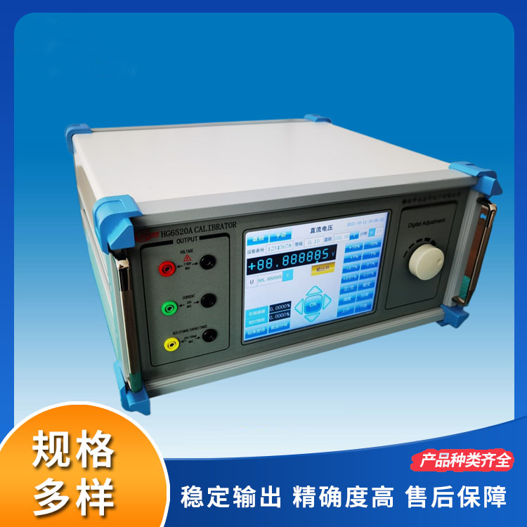


The HG6503 multifunction precision calibrator is a multi-range, wide-range, high-precision seven-and-a-half-digit output and display calibrator. This instrument can output high-accuracy DC voltage/current, AC voltage/current, DC power, and AC power with power factor control. It also features resistance simulation and capacitance simulation functions. It is suitable for calibrating or verifying various voltage meters, ammeters, wattmeters, power factor meters, phase meters, frequency meters, multimeters, multimeters, AC/DC clamp meters, and various power measurement transmitters with accuracy below 0.05. It can also be used as a standard source. The instrument fully complies with the relevant requirements of JJG 124-2005 "Regulation for Verification of Ammeters, Voltmeters, Wattmeters, and Resistance Meters," JJF 1075-2015 "Specification for Calibration of Clamp Ammeters," JJF 1587-2016 "Specification for Calibration of Digital Multimeters," JJF 1284-2011 "Specification for Calibration of AC/DC Meters," GB/T 15637-2012 "General Specification for Verification Devices of Digital Multimeters," GB/T 15481-2000 "General Requirements for the Competence of Testing and Calibration Laboratories," and JJF 1059.1-2012 "Expression and Evaluation of Measurement Uncertainty." It is widely used in quality control, metrology, research and teaching, and instrument maintenance in industrial and mining enterprises, aerospace, research institutions, railways, power companies, and schools.
II. Main Features and Characteristics
The following instruments are verifiable by this device: indicator gauges, AC/DC voltage meters, AC/DC ammeters, AC/DC power meters, power factor meters, phase meters, resistance meters, capacitance meters, frequency meters, clamp-on meters, and pressure or temperature transmitters, etc.
2.1 DC/AC voltage output peak: 1100V, current peak: 30A, AC frequency range: 45Hz to 1kHz.
2.2 Simulation Resistance Range: 0~200MΩ; Simulation Capacitance Output Range: 1nF~200uF; Continuously adjustable.
2.3 Accurately outputs DC power, AC active power, apparent power, and power factor.
2.4 High load capacity, ensures stable and accurate values under full load conditions, capable of covering the calibration of analog meters.
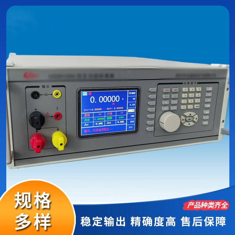
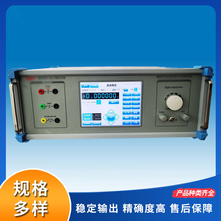
2.5 Features direct input of output values, potentiometer adjustment, rotary encoder, and step ratio for various value adjustments.
2.6 Equipped with a large LCD touch screen, the value display is intuitive and the operation is very convenient.
2.7 DC/AC Voltage Output Range: 0-1000V.
2.8 DC/AC Current Output Range: 0-30A.
2.9 AC/DC Resistance Output Range: 0 ~ 200M
2.10 DC/AC Capacitance Output Range: 0-200uF
2.11 Equipped with factory-standard coils, the clamp meters can verify AC/DC clamp meters, with a verification range of 0~1000A.
2.12 Features comprehensive hardware and software protection, enhancing the long-term reliability of the equipment.
2.13 DC output polarity can be changed; a smooth change mode is available for calibrating pointer-type meters.
2.14 This instrument can be smoothly upgraded and additional features can be added. Please contact our company for more information.
Section 3: Main Technical Specifications
3.1 DC Voltage Technical Specifications (20℃ ± 2℃):
Range | Adjust Fineness | Accuracy ± (Reading Value % + Full Scale %) | Wavy texture Coefficient | Load Capacity | |
Rated Value | Peak | ||||
75mV* | 5ppm | 0.012%RD+0.008%RG | <0.05% | 100 mA | 1000 mA |
200mV | 200 mA | ||||
2V | 0.003%RD+0.002%RG | 500 mA | |||
20V | 200 mA | ||||
200V | 0.012%RD+0.008%RG | 50 mA | |||
1000V | 50 mA | 300 mA | |||
* Among them, the additional error below 7.5mV is ±7.5μV.
3.2 DC Current Technical Specifications (20°C ± 2°C):
Range | Adjust fineness | Accuracy ± (Reading Value % + Full Scale %) | Wavy texture Coefficient | Load Capacity |
200uA | 5ppm | 0.012%RD+0.008%RG | <0.2% | 50V |
2mA | 0.007%RD+0.003%RG | |||
20mA | ||||
200mA | ||||
2A | 0.012%RD+0.008%RG | |||
10A | 30V | |||
30A | 0.03%RD+0.02%RG |
3.3 Technical Specifications for AC Voltage (20℃ ± 2℃):
Range | Load Capability | Adjust Fineness | Accuracy ±(Reading Value % + Full Scale %) | Distortion | |
45-400Hz | 400-1000Hz | ||||
200 mV | 800 mA | 50ppm | 0.03%RD+0.02%RG | <0.2% | |
2 V | 0.02%RD+0.01%RG | 0.03%RD+0.02%RG | |||
20 V | |||||
200 V | 500 mA | ||||
1000 V | 200 mA | 0.03%RD+0.02%RG | |||
Test measurements can be performed using a dedicated shielded cable for voltage limits below 10V, which can enhance output accuracy.
3.4 Technical Specifications for AC Current (20℃ ± 2℃):
Range | Load Capability | Adjust Fineness | Accuracy ± (Reading Value % + Full Scale %) | Distortion | ||
45-400Hz | 400-1000Hz | |||||
2mA | 36V | 50ppm | 0.03%RD+0.02%RG | <0.2% | ||
20 mA | ||||||
200 mA | 50V | 0.02%RD+0.01%RG | 0.03%RD+0.02%RG | |||
2A | ||||||
10A | 20V | |||||
30A | 0.03%RD+0.02%RG | |||||
Below 100mA, the use of a dedicated shielded cable for testing and measurement can enhance output accuracy.
3.5 Technical Specifications of AC/DC Clamp Meters (20℃ ± 2℃)
Range | Load Capability | Adjust Fineness | Accuracy ±(Reading Value % + Full Scale %) | Distortion Rate | ||
50Hz | 400Hz | 1kHz | ||||
20A | 1.3V | 50ppm | 0.03%RD+0.02%RG | 0.06%RD+0.04%RG | <0.2% | |
100A | ||||||
200A | ||||||
500A | ||||||
1000A | —— | |||||
3.6 Power, Power Factor, Phase, Frequency Technical Specifications (20℃ ± 2℃):
Project | Scope | Accuracy |
Communication Power | 1W to 30kW continuous adjustable | PF = ±0.8 to ±1 (50Hz), < 0.05% FS PF = ±0.8~±0.5 (at 50Hz), < 0.1%FS |
Direct Current Power | 1W to 30kW continuous adjustable | 0.02%FS |
Power Factor | Continuous adjustable from 1 to -1 | <0.05% |
Phase | 0~360° | <0.02° |
Frequency (Sine Wave) | 45Hz~200Hz | <0.02% |
200Hz~600Hz | <0.03% | |
600Hz~1000Hz | <0.05% |
Communication Power Evaluation Scope:
Voltage: 30V, 100V, 300V, 600V
Current: 1A, 2A, 5A, 10A, 20A
Frequency: 50 Hz
Power Range: Combination of voltage range and current range (AC voltage greater than 10V, AC current greater than 100mA).
Note: FS = Voltage Range × Current Range.
3.7 Simulation Resistance Technical Specifications (20℃ ± 2℃):
Range | Resolution | Short-term stability (%RG/min) | Accuracy within one year ± (Reading Value % + Full Scale %) |
20Ω | 1mΩ | 0.02 | 0.05%RD+50mΩ |
200Ω | 10mΩ | 0.01 | 0.03%RD+0.02%RG |
2kΩ | 0.1Ω | ||
20kΩ | 1Ω | ||
200kΩ | 10Ω | ||
2MΩ | 0.1kΩ | ||
20MΩ | 1kΩ | 0.05 | 0.12%RD+0.08%RG |
*200MΩ | 10kΩ | 0.1 | 0.6%RD+0.4%RG |
Please use a dedicated shielded test cable for resistance measurement.
To ensure stability of resistance measurement readings, please use a four-wire measurement method for resistances below 1kΩ.
Over 100MΩ can be measured but accuracy is not assessed.
3.8 Simulation Capacitor Technical Specifications:
Capacitance Range | Short-term stability (%RG/min) | Accuracy within one year ±(Read Value % + nF) | Frequency Range |
0.8nF~1nF | 0.2 | 0.5%RD + 0.1nF | 10K~50K |
1nF~10nF | 0.2 | 0.5%RD + 0.3nF | 750Hz~2.5K |
10nF~20nF | 0.1 | 0.5%RD + 0.2nF | 500Hz~2K |
20nF~200nF | 0.05 | 0.2%RD + 0.5nF | 500Hz~2K |
200nF~1μF | 0.05 | 0.2%RD + 1nF | 200Hz~1K |
1μF~10μF | 0.05 | 0.2%RD + 10nF | 75Hz~200Hz |
10μF~100μF | 0.1 | 0.5%RD + 50nF | 50Hz~100Hz |
100μF~200μF | 0.1 | 0.5%RD + 200nF | 50Hz~75Hz |
3.9 Other Technical Specifications:
Weight: ≤ 16kg (excluding accessories and packaging box)
Volume: 480mm x 420mm x 135mm
Working Voltage: AC 220V ±10%
Work Environment: Temperature -20 to 40°C; Relative Humidity ≤ 85%.