

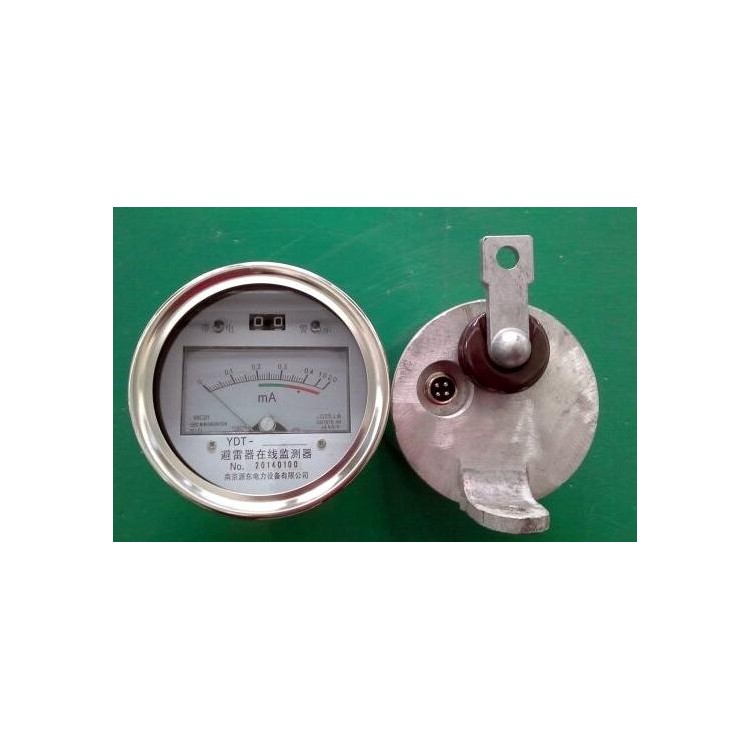


YDT Communication Surge Arrester Online Monitor, our newly designed surge arrester monitor with RS485 bidirectional communication function, fully meets the requirements of international standard IEC. Technical specifications are identical to the original JSH/JCQ models, capable of recording the operation times of surge arresters and monitoring the leakage current online. It also features a 485 communication interface, enabling real-time transmission of surge arrester operating parameters such as leakage current magnitude, operation times, and operation time to the main control room. This allows for early detection of potential accidents, thereby preventing their occurrence.
II. Structural Features
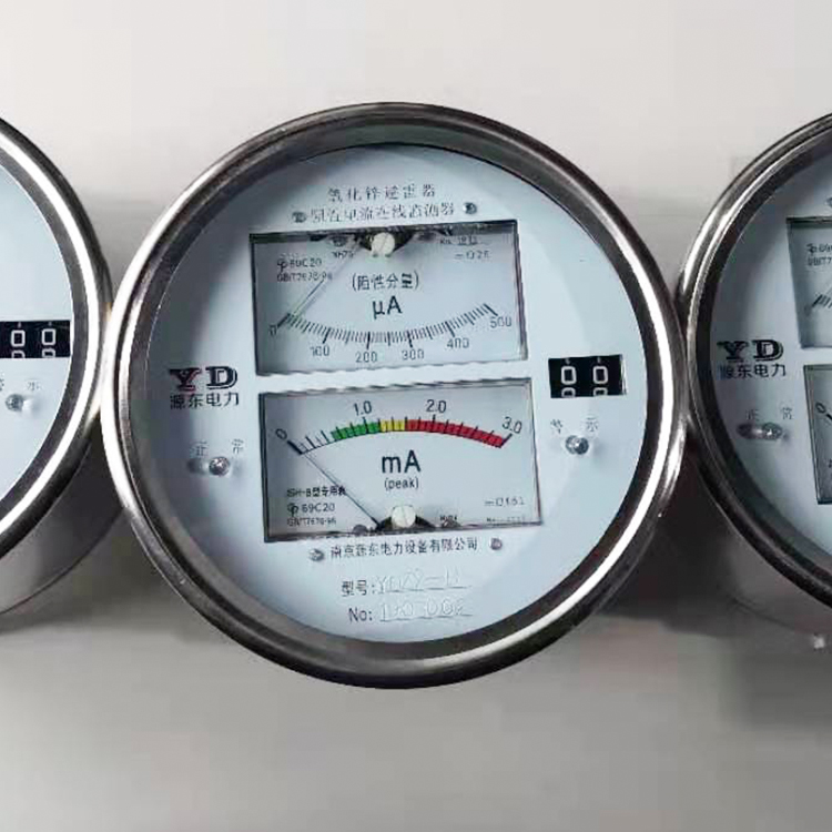
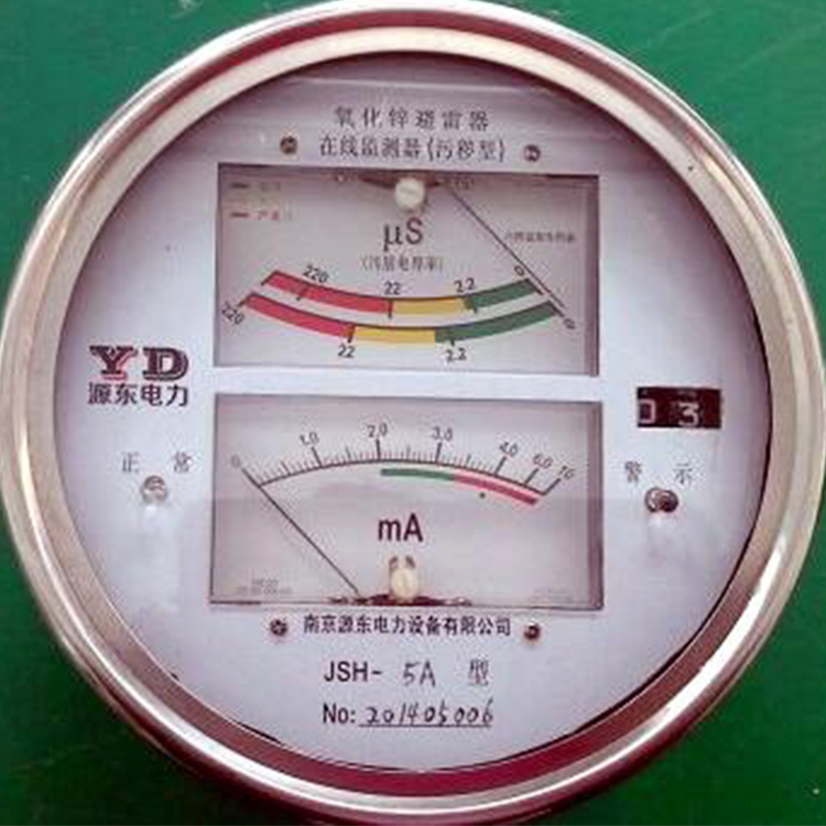
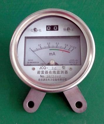
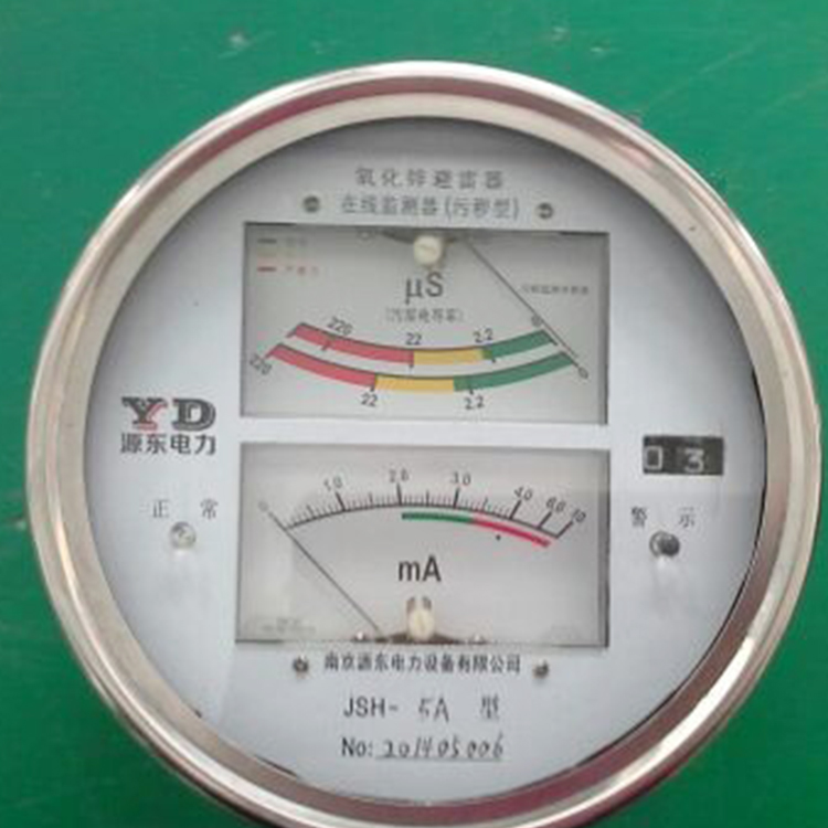
◆Accurately measure the continuous current (leakage current) of lightning arresters and the number of operations of the arresters.
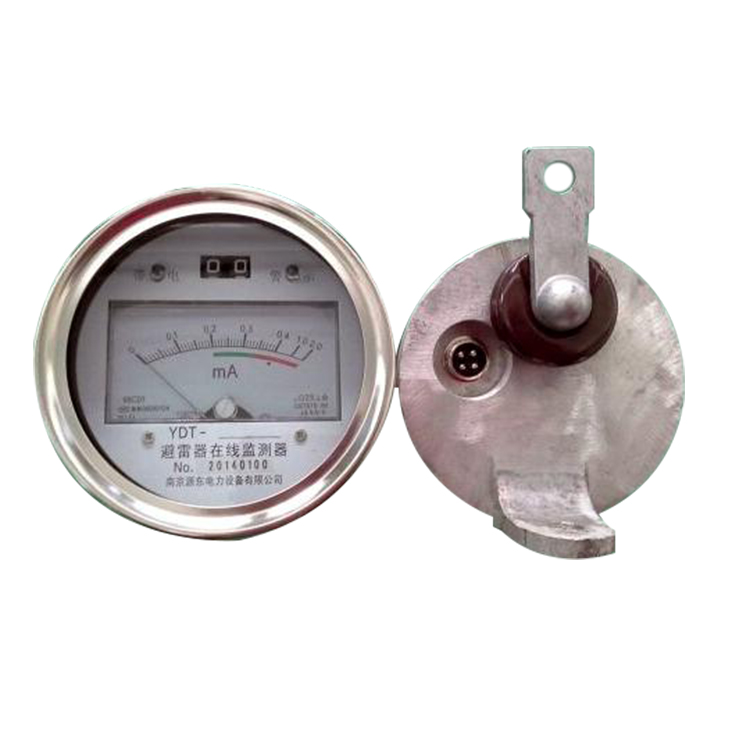
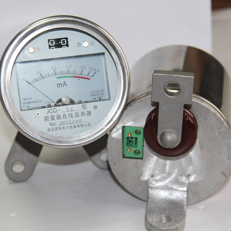
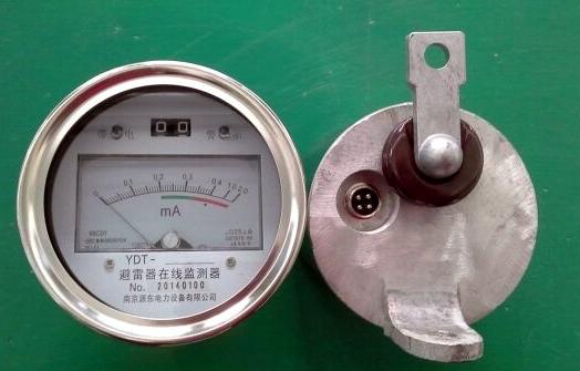
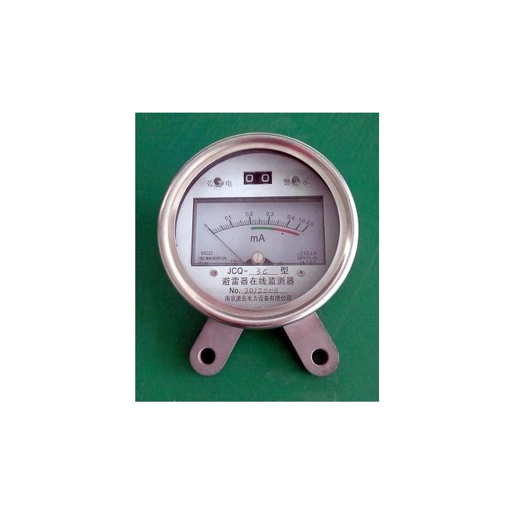
Stainless steel housing, aesthetically pleasing and stylish. Circular structure with excellent sealing properties.
The leakage current meter features a color-coded scale and a charged warning indicator light for easy observation.
◆ Features an RS485 external measurement socket for signal transmission, facilitating centralized monitoring.
3. Key Electrical Properties
Due to the use of a new type of zinc oxide valve, it features low residual voltage under rated current, high square wave conduction capacity, high impedance under continuous operating voltage, and high capacity for withstand AC overcurrent under abnormal conditions.
Electrical Performance Table:
4. Product Inspection Methods
Counter and Milliampere Meter Test
Charge a 10uF capacitor to 200-600V using a 500V megohmmeter or other DC power source, then discharge it across the counter terminals. The counter should operate reliably and the milliammeter needle should swing; the milliammeter can also be tested with a digital multimeter, setting the multimeter to the diode mode, with the two test leads connected to the monitor terminals. The milliammeter should indicate several hundred microamperes for normal operation.
2. Communication Function Testing
Use an RS485 to RS232 serial port converter. Connect the power voltage DC12V to the signal output interface 1 (red, positive) and 2 (yellow, negative). Connect communication lines A+ and B- to pins 4 (blue) and 3 (green), respectively. Plug the converter into the computer's serial port.
V. Communication Protocols
Serial Port Baud Rate: 9600, Parity: NONE, Data Bits: 8, Stop Bits: 1
Common Command 1:
1. 04 Directive (Master station requesting monitoring data from a slave station [monitor])
Command Format: Module Address-Function Code (04)- Start Address MSB - Start Address LSB - Data Count MSB - Data Count LSB - Check Code
Response Format: Module Address-Function Code (04)- Number of bytes - Data (16-bit) - Data (16-bit) - Checksum
Instruction 300400 80 00 02 CRC_H CRC_L; Require current and lightning strike data for two parameters
Response 300404 Count High (00) Count Low I_H I_L CRC_H CRC_L
30 04 0400 05 25 DF 90 4E
00 05 - Number of Actions Hexadecimal
25 DF for current size Hexadecimal
Current I = 9695/1000 = 9.695 mA
90 4E is the check code
00080 = Discharge Count Value, 00081=Full Current Value, 00082 = Resistive Current Value, 00083 = Module Address Value.
Very common command 2/3:
2. 06 Command (reset parameters from a master computer to a specific slave device (monitor), including: counter value, slave device address, and measurement value calibration coefficient)
Parameter Code: 00080 = Discharge Count Value; 00083=Module (Slave Device Address); 00084 = Encrypted; 00085=Calibration Coefficient 1; 00087=Coefficient Value
Revise the discharge meter readings
Command: 30 06 00 80 00 10 CRC_H CRC_L (where 30 is the address, 06 is the function code, 00 80 is the parameter code, and 00 10 is the discharge count)
Response: 30 06 00 80 00 10 CRC_H CRC_L
Example 2: Modify Subordinate Device Address
Command: 30 06 00 83 00 32 CRC_H CRC_L (where 00 83 is the parameter code, 00 32 is the new address)
Response: 30 06 00 83 00 32 CRC_H CRC_L
Example 3: Adjust Calibration Factor 1 (for Full Current)
Command: 30 06 00 85 00 64 CRC_H CRC_L (where 00 85 is the parameter code and 00 64 is the new calibration coefficient)
Response: 30 06 00 85 00 64 CRC_H CRC_L
Example 4: Review Coefficient
Command: 30 06 00 87 00 02 CRC_H CRC_L (where 00 87 is the parameter code, 00 XX is the calibration coefficient)
Response: 30 06 00 XX 00 XX 00 00 CRC_H CRC_L
3. Send Command Automatically 05
Strike sends command 30 05 04 00 actively06 25 DF 61 9F
Current exceeds boundary, actively send command 30 05 04 0006 25 DF 61 9F
Note: During the installation of the YDT lightning arrester online monitoring, please record the serial numbers and line names for easy matching during software backend setup.
Section 6: Outline Structure and Installation Dimensions
Elevation structure diagram:
The YDT communication-type surge arrester online monitor is housed in a stainless steel metal shell, offering excellent corrosion resistance and electromagnetic shielding. The front glass is sealed with silicone rubber. Suitable for both indoor and outdoor installations. The monitor is secured using two M10 bolts through the bottom mounting holes, which also serve as the grounding terminal. The high-voltage output is led out through a small porcelain sleeve and connected to the bottom of the surge arrester with an M10 bolt cap.
Section 7: Safety Measures
Within the monitor, the 485 computer communication board transmits signals to the monitor through opto-isolation, with a voltage withstand of 1500V (residual voltage of the monitor less than 800V). To further enhance safety measures, a fiber optic isolation 485 to 232 converter is used when connecting the signal lines of all monitors to the computer, adding several meters of fiber optic cable to reliably prevent overvoltage intrusion.
The communication line uses a four-core shielded wire, or a standard Ethernet cable can be used. Each power line and ground wire uses three, and the signal lines use two. All monitors are connected with a single line (in parallel). Connected to a PC via an RS485 to RS232 converter. The software is programmed according to the RS485 communication protocol, and data (leakage current and operation times of the surge protector) are regularly queried. An alarm current value can be set; an alarm signal is triggered when the current exceeds this value.