


DC Reduction Motor
I. Product Overview
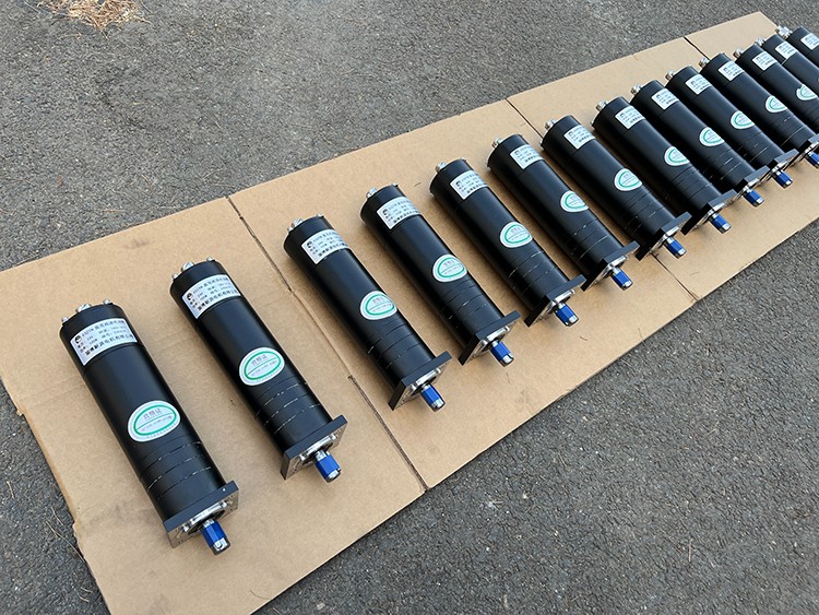
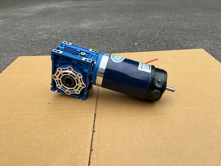
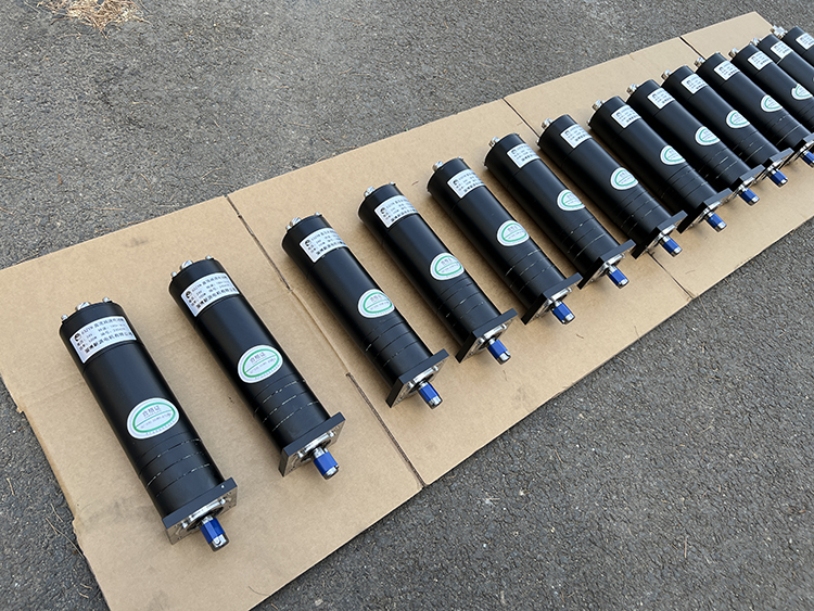
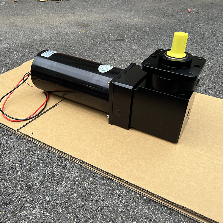
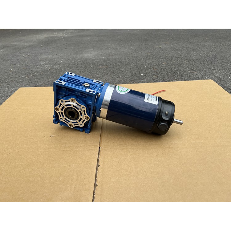
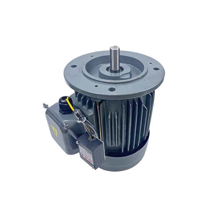
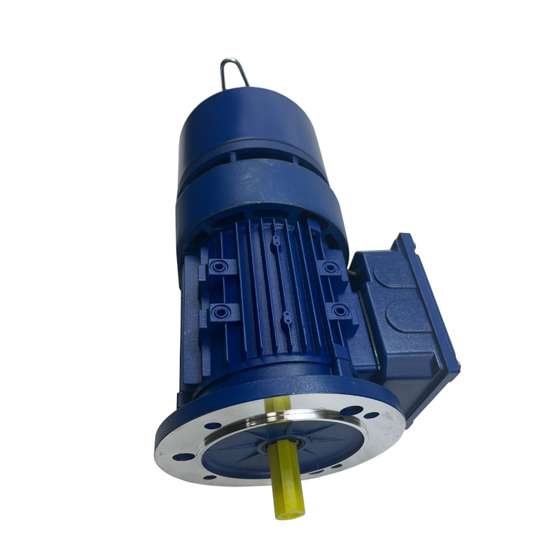
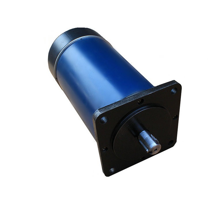
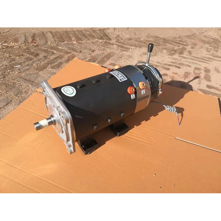
Based on a standard DC motor, this product includes a matching gear reducer. The gear reducer's function is to provide a lower speed and greater torque. Additionally, the gear box's varying reduction ratios offer different speeds and torques. This significantly enhances the usage of DC motors in the automation industry. A reducer motor refers to an integrated unit of a reducer and a motor (motor). This integrated unit is often also called a gear motor or a gear motor. Typically, it is assembled and supplied as a complete set by professional reducer manufacturers. Reducer motors are widely used in the steel industry, machinery industry, and more. The advantages of using reducer motors include simplified design and space-saving.
II. Features
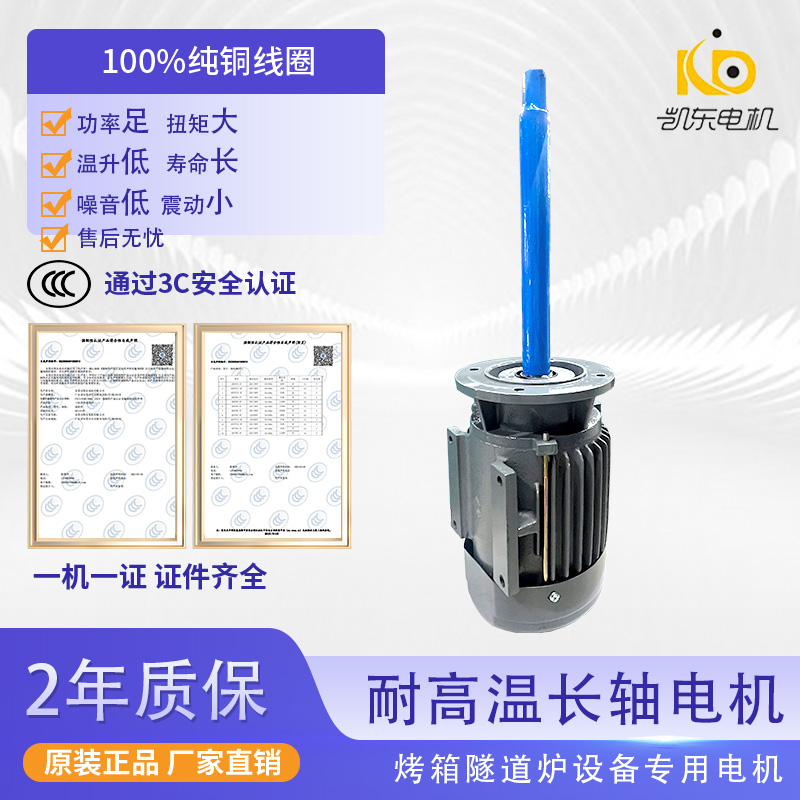
1. Designed with technical requirements, the decelerating motor combines high technology content.
2. Space-saving, reliable and durable, with high overload capacity, power up to 95KW and above.
3. Low energy consumption, superior performance; the reducer efficiency exceeds 95%.
4. Low vibration, low noise, high energy efficiency, with high-quality section steel material, rigid cast iron housing, and gears surface treated with high-frequency heat treatment.
5. Precision machining ensures precise positioning, all of which forms the gear drive assembly. The gear reduction motor is equipped with various motors, creating an integrated mechanical and electrical system, fully guaranteeing the product's quality characteristics.
6. The product incorporates a series of modular design concepts, offering wide adaptability. This series features a variety of motor combinations, installation locations, and structural options, allowing for the selection of any speed and various structural forms to meet actual needs.
Section 3: Quantity of Main Components
1. Gearbox section:
There is a significant difference in price according to types, mainly including gears, bearings, worm gears, and worm shafts.
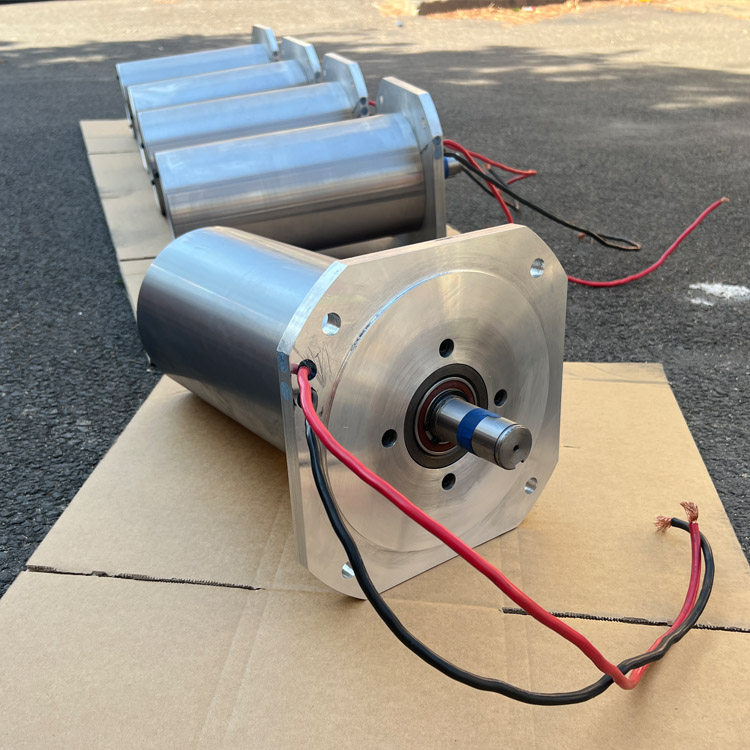
2. Motor Section:
Stator: (1) Main pole. (2) Commutator pole. (3) Base. (4) Brush assembly.
Rotor: (1) Armature Core. (2) Armature Winding. (3) Commutator. (4) shaft.
Torque Calculation Formula
1. Knowing the motor power, speed ratio, and usage coefficient, calculate the reducer torque using the following formula:
Reducer Torque = 9550 x Motor Power - Motor Power Input Speed x Reduction Ratio x Usage Factor
2. Knowing the torque, output speed of the reducer, and the use coefficient, the required motor power for the reducer can be calculated using the following formula:
Motor Power = Torque / 9550 x Motor Power Input Speed / Ratio / Usage Factor