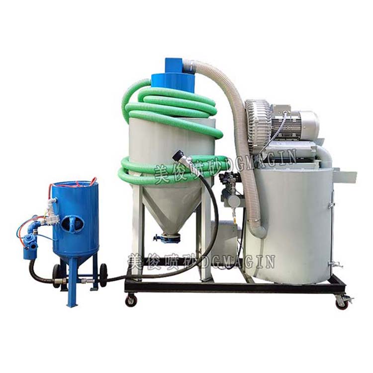


The dust removal system consists of components such as suction and exhaust ducts, suction ports, modular filter cartridge dust collectors, exhaust fans, and exhaust chimneys.
The working principle of the dust removal system:
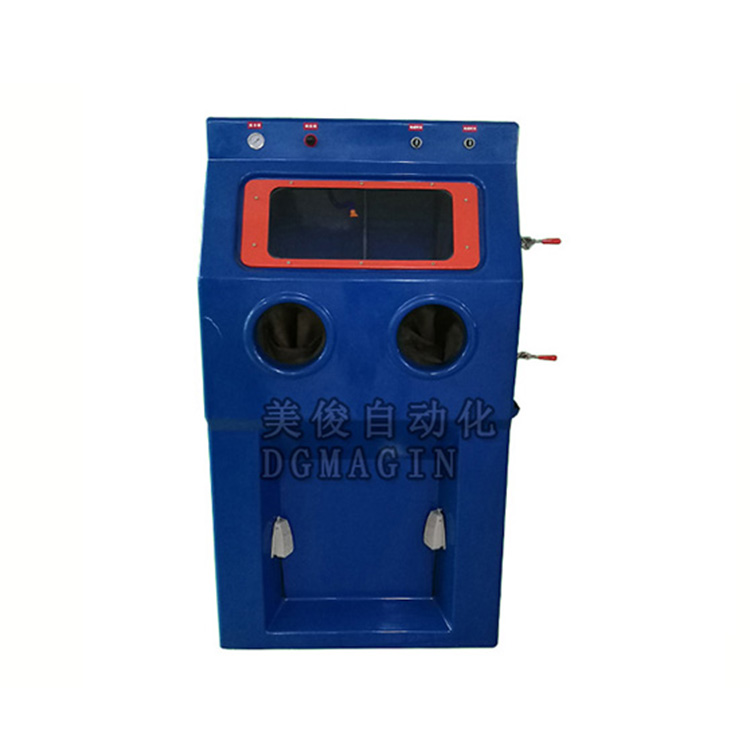
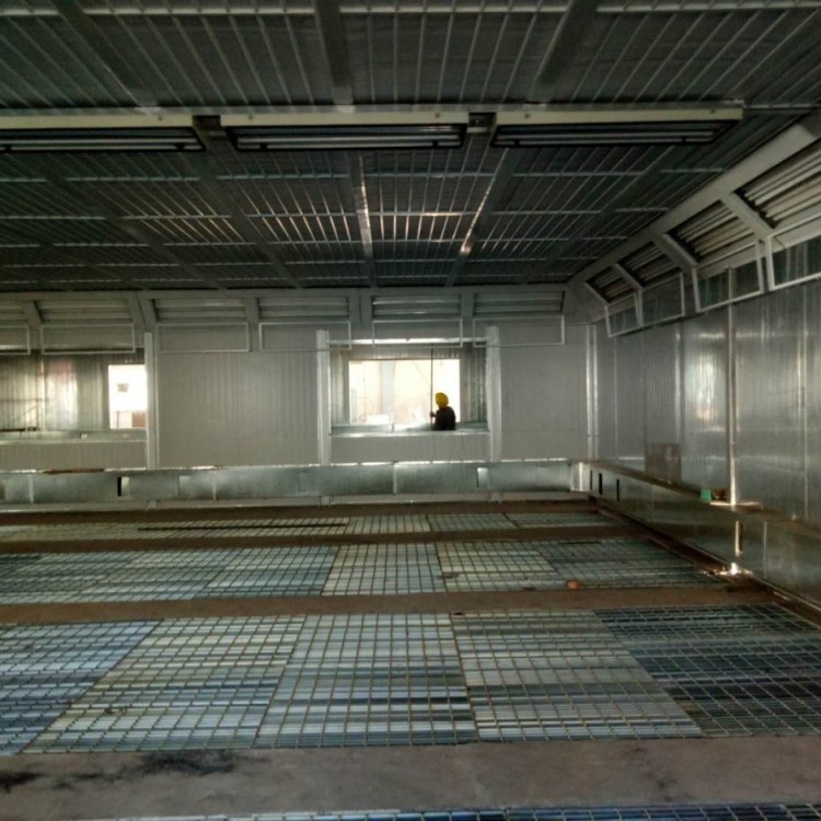
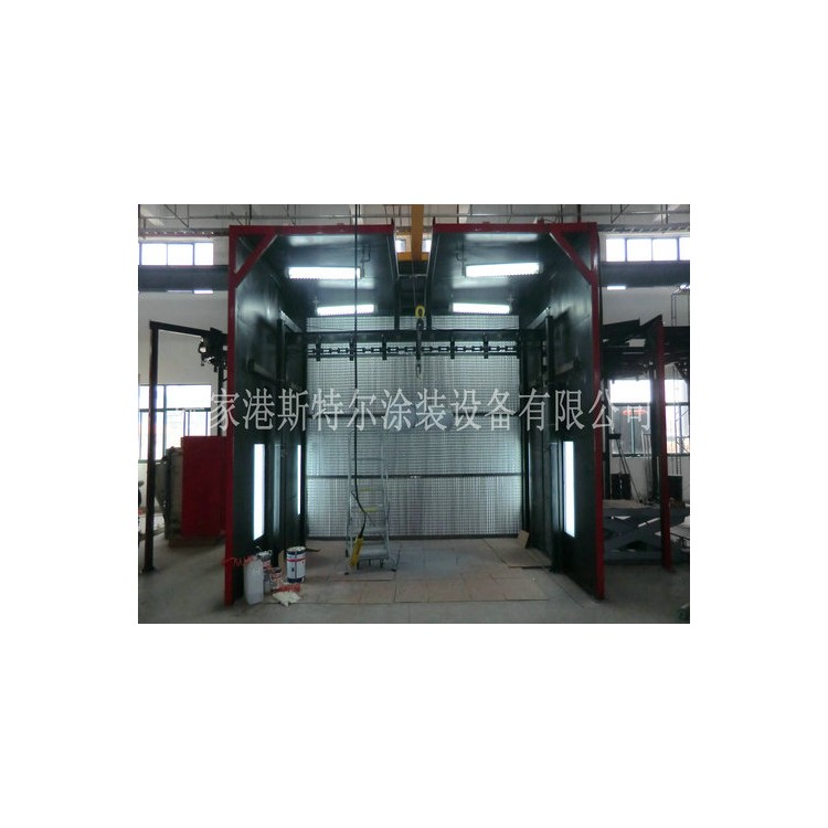
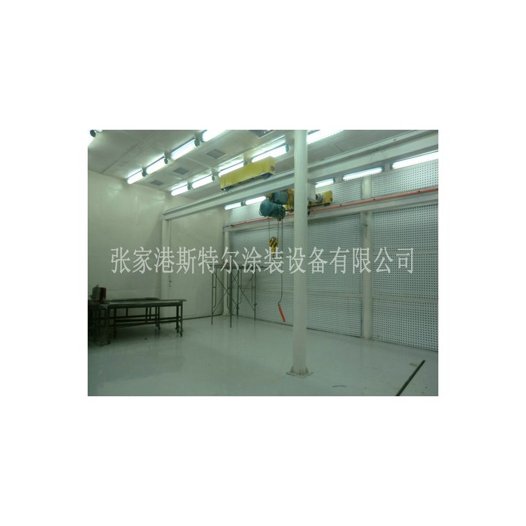
The dust removal system in the sandblasting room employs an upward air intake and downward exhaust, circulating dust suction method. Clean air enters the sandblasting chamber from the top of the room, and the dust removal fan draws impure gases inside the room through various suction ports into the dust collector for collection and processing.
Due to the dust suction inlet of the environmental-friendly pneumatic recovery sandblasting room being fully positioned below the honeycomb sand collection floor, the airflow carries the dust in a continuous upward-downward movement. Consequently, the dust is always confined to the lower part of the sandblasting room, resulting in a low dust concentration in the space above 0.5 meters, and providing a favorable working environment.
The dust extraction fan's duct can be terminated into the exhaust flue as required, meeting the standard requirements for compliant emissions.
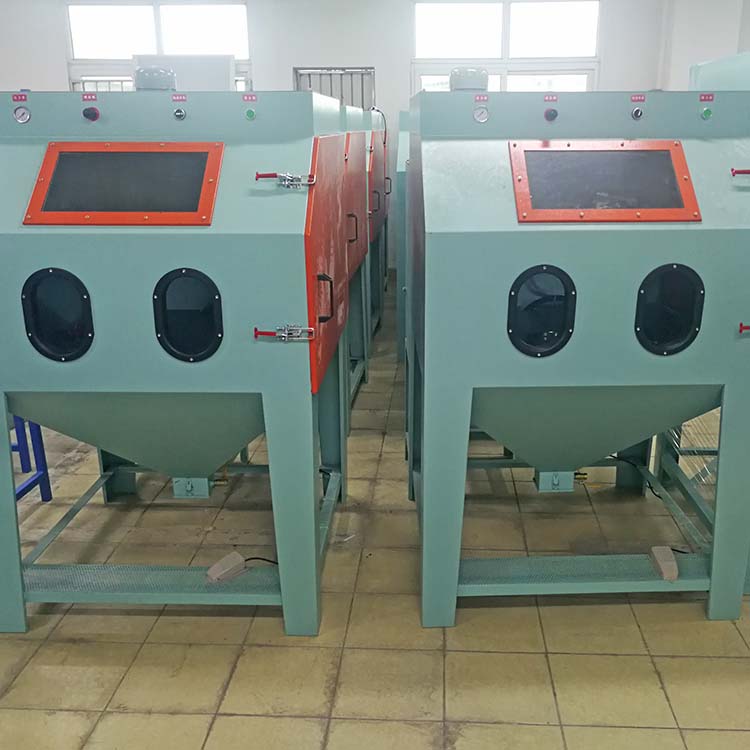
Due to structural reasons, traditional shot blasting rooms typically locate the dust extraction ports at the top, resulting in a dust flow from bottom-up or horizontally. Consequently, during sandblasting operations, the dust concentration inside the shot blasting room remains high, visibility is low, and the working environment is poor.
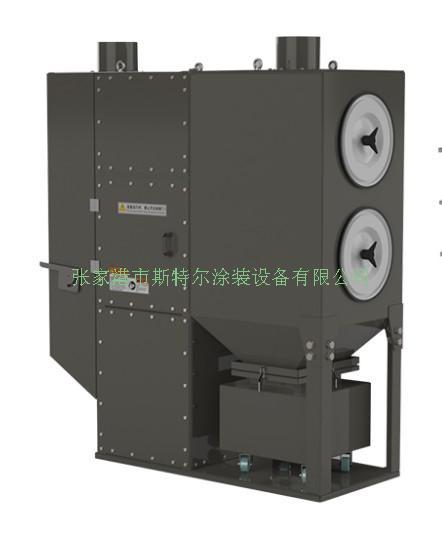
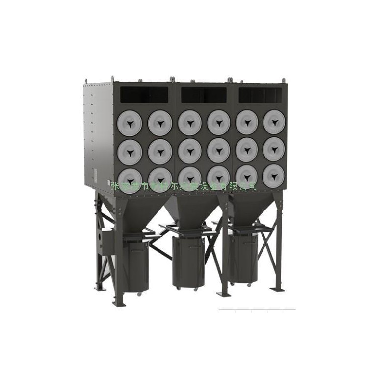
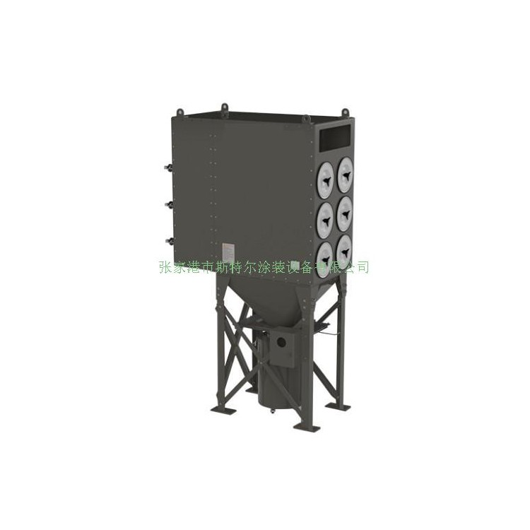
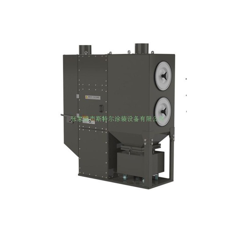
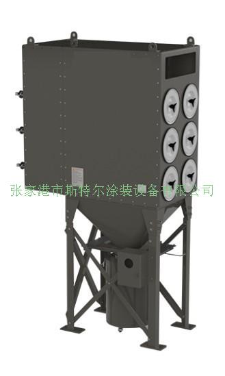
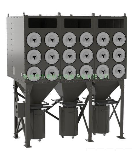
Modular filter cartridge dust collector
Modular filter cylinder dust collectors are a key component in the sandblasting booth dust removal process; their operational status directly impacts both indoor environment and outdoor emission standards.
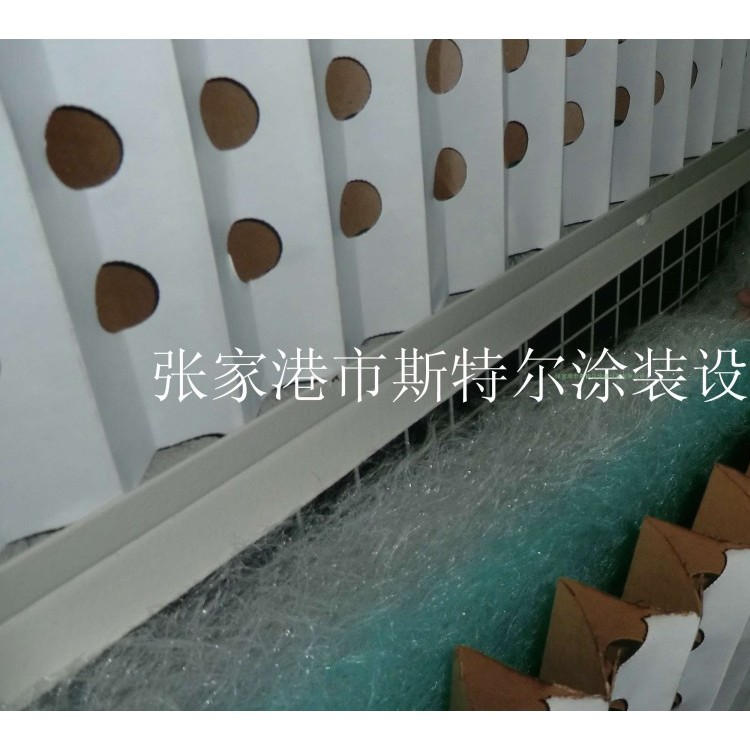
The filter element arrangement is logically designed, with high-pressure pulse air-purge cleaning, yielding excellent results; this structure facilitates the even distribution of dusty gas among the filter elements inside the dust collector, and also aids in the immediate fall of dust ejected during the back-purge cleaning, reducing the likelihood of secondary adsorption.
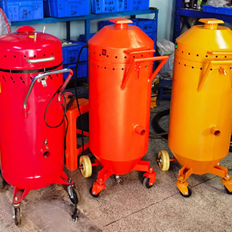
The dust collector is equipped with a mobile dust collection hopper, featuring a quick connection structure with the collector. It is well-sealed and easy to open, allowing cleaning workers to easily open it, pull it to the designated area for dust disposal, and complete the cleaning task even when the dust collection system is in operation. It avoids secondary dust飞扬 caused by transporting in other containers, thus preventing environmental pollution.
This dust collector meets national environmental protection standards with an emission of ≤120mg/m³, capturing particles with a size of <5um, resistance of <400Pa, excellent air permeability, low resistance, low energy consumption, and reliable filtration performance.
The dust collector features an aesthetically pleasing, refined, and stable overall design structure. The filter cartridges are assembled using a high-speed connection method, making disassembly and assembly extremely convenient, thereby reducing the physical labor intensity of workers and improving working conditions.
All filter cartridges are made of imported filter materials, featuring the following performance characteristics:
Filter Material: Polyester Fiber, Thickness 0.75mm
High-Temperature Resistance: 80℃
Air Permeability: 220 m³/m²/h
Weight: 240g/m²
Filter Precision: 0.5um - 5um
Filter Resistance: ≤45 Pa
As shown in the figure, the filter element is structured into a folded cylindrical shape with an outer diameter of 325mm, an inner diameter of 220mm, and a height of 660mm. A standard filter element has a filtration area of 12m², whereas a dust removal bag of the same size has only a filtration area of 0.6m². Therefore, using a filter element-based dust collector can significantly reduce the volume of the dust collector, saving space in terms of equipment footprint.
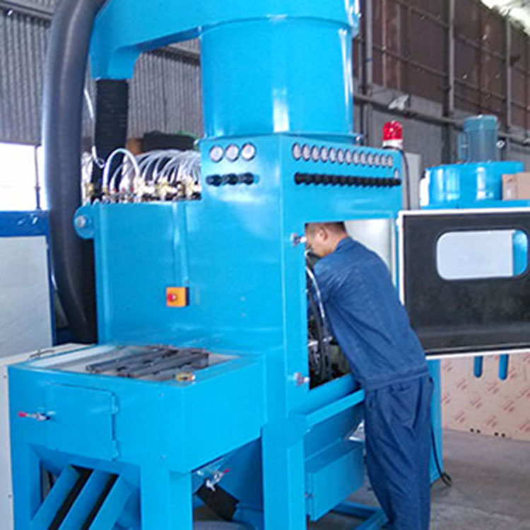
The dust collector's cleaning method is a key technology for its efficient operation. This dust collector employs a pulse reverse-jet cleaning method. The working principle is as follows: when the pulse controller sends a signal, the pulse control valve's exhaust port opens, releasing the pressure of the gas in the back pressure chamber of the pulse valve, creating a pressure difference on both sides of the diaphragm. Due to the pressure difference, the diaphragm moves, the pulse valve opens, and compressed air is then released through the pulse valve and out of the nozzle (the gas emitted from the nozzle is called the primary air). As the high-speed airflow passes through the Venturi tube inducer, it induces several times the amount of surrounding air (referred to as secondary air) into the filter cylinder, creating an instantaneous positive pressure inside the cylinder, thus achieving the cleaning purpose. The frequency and number of the automatic pulse reverse-jet, including the reverse-jet time, are all controlled electrically and can be flexibly adjusted according to actual usage requirements.
By increasing the dust collector's filter area, the filter air velocity can be reduced, thereby lowering the dust emission. This filter tube dust collector has a filter air velocity of 0.5-0.9 m/min.
The dust collector is composed of a storage ash barrel and a handcart, allowing operators to conveniently transport the waste inside the ash tube to the disposal location.