


Design Principles:
Utilize reliable production technology and equipment, along with modern management, to replace traditional, outdated painting processes, equipment, and management. Meet requirements for painting processes, paint quality, environment, hygiene, and production standards; equipment is reliable, advanced, aesthetically pleasing, economically operational, easy to operate, and convenient.
Principles for Paint Shop Layout Design:
The manual and non-manual operation areas are relatively separated.
2. Clean and non-clean zones are relatively separated.
3. Minimize the volume of shipping.
Minimize noise pollution as much as possible.
Process Design:
Based on the absorption and digestion of advanced domestic and international coating technologies and mature experiences, ensure that this process design is practical, reliable, and advanced.
Equipment design and manufacturing are strictly in compliance with national standards related to environmental protection, hygiene, and safety. Noise reduction measures are implemented for all equipment, ensuring noise levels in the workshop are below 85 decibels.
The equipment meets the product's usage requirements, operates reliably, is easy to operate, and convenient for maintenance and upkeep.
The selected accessories, materials, and electrical components are all top domestic brands, ensuring reliable quality and guaranteeing the equipment's performance and service life.
Consider the interconnectivity between systems and implement protective measures against equipment failures to prevent accidents.
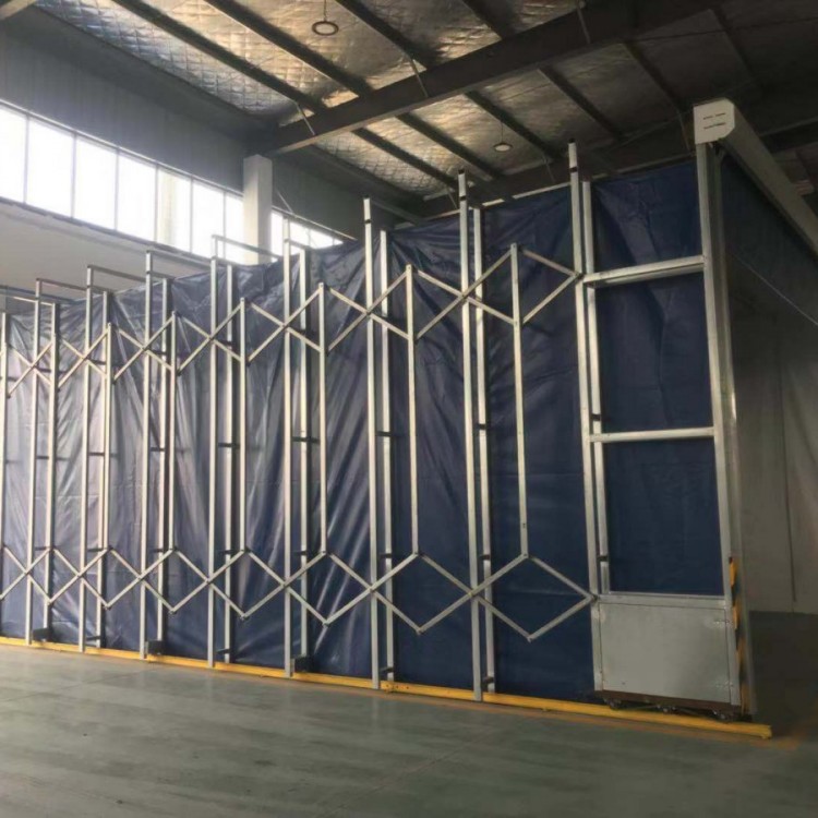
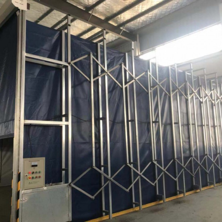
(6) The spray booth employs a dry spray booth with top air supply and bottom exhaust.
Equipment Description and Structural Design
1. Working Principle:
During painting, external air is filtered through a primary filter net via the intake vent and then blown to the ceiling by a blower (heating system activated during winter). This allows the gas to uniformly fill the paint room after entering the static pressure chamber through a filter pad, creating a wind curtain around the workpiece. At this point, the wind speed in the paint room is above 0.23 m/s, ensuring that paint mist from the painting process does not linger in the operator's breathing zone but quickly descends. Subsequently, the air flow is directed through the exhaust fan and through the exhaust gas treatment system to the exhaust duct, then out through an environmental protection box, in compliance with the GB16297-1996 standard.
2. Main structure and components of the equipment
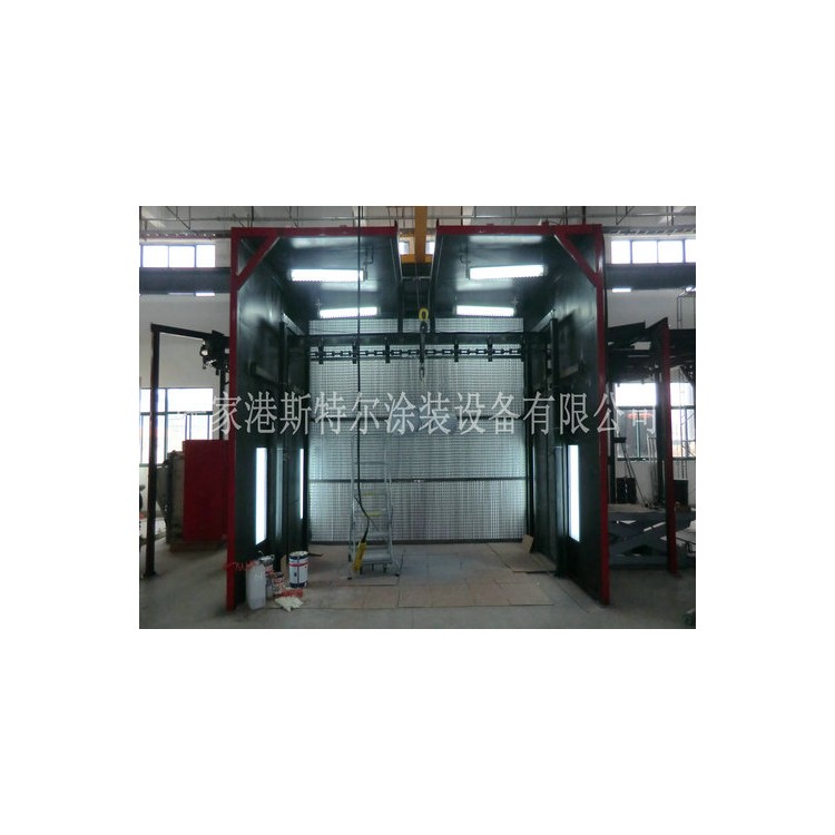
Structural Composition: Consists of several components, including the room body, lighting system, air filtration system, air distribution system, heating system, exhaust system, paint mist and waste gas treatment system, electrical control system, and safety system.
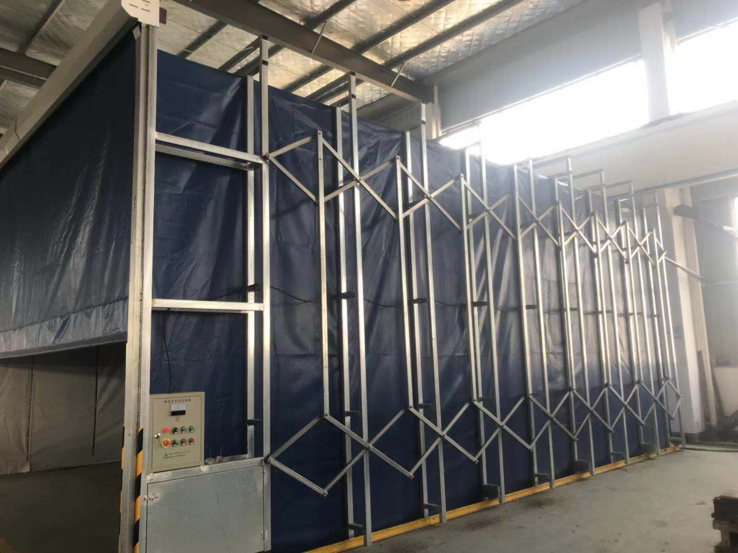
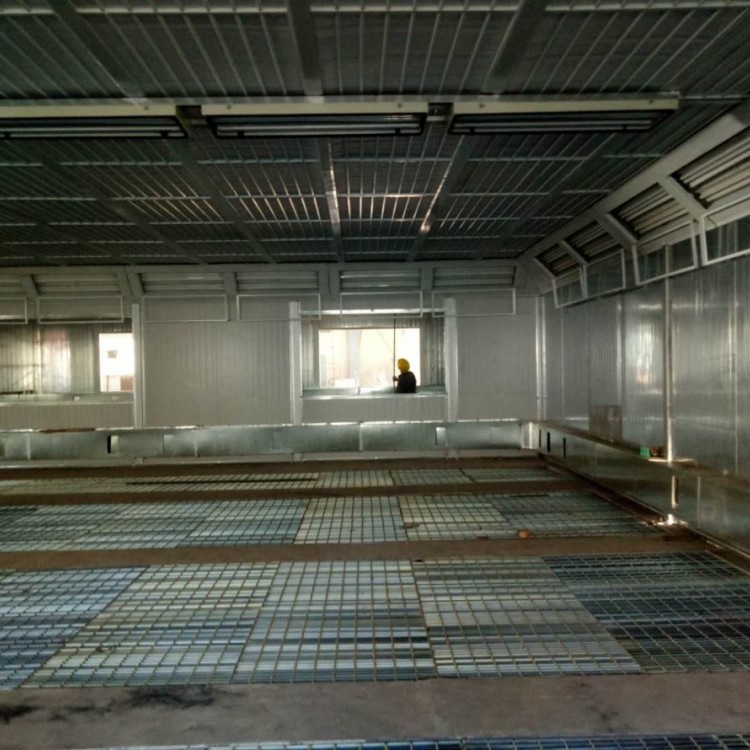
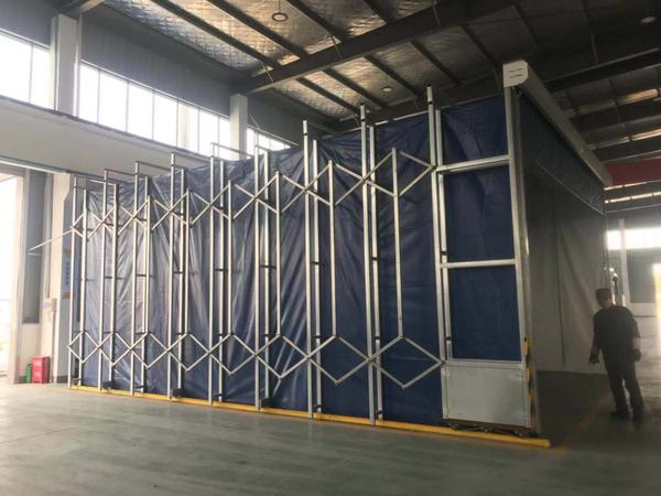
2.1 Body: Composed mainly of the frame, wall panels, access doors, and safety doors. The body meets the national or relevant industry standards in terms of strength, stability, thermal insulation, sealing, impact resistance, and seismic resistance.
⑴ Skeleton
The chamber frame is constructed from square steel tubes and galvanized steel plates, bent and welded together.
⑵ Wall Panel
The room panels are made of composite thermal insulation boards, with both inner and outer plates being color steel plates, filled with 58mm thick polyurethane insulation material. Total thickness is 75mm. All panels are assembled in a modular structure for easy installation and disassembly. The color is white.
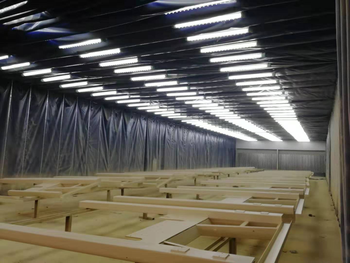
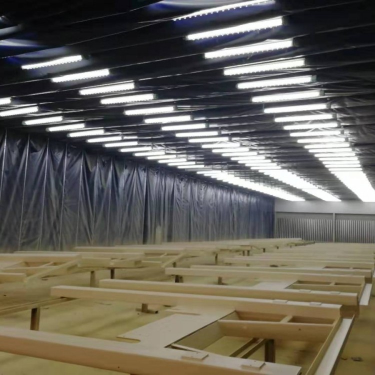
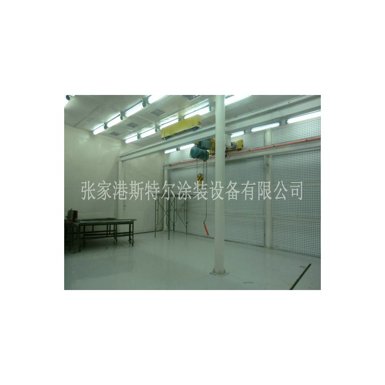
Lighting System: Explosion-proof lighting units are installed on the top and waist sides of the room. The top side units are mounted at a 45-degree angle, while the waist side units are installed within the wall panels. The tubes utilize explosion-proof Philips high-efficiency sources, ensuring safety, energy-saving, and easy maintenance. The ballasts are designed by our company specifically for spray rooms, guaranteeing an illumination intensity of approximately 700Lux.
Each side of the waist features two layers of lighting arrangement.
2.3 Air Filtration System
Air filtration is of two stages, including preliminary filtration (inlet air filtration) and high-efficiency filtration (top filtration). The preliminary filtration is set at the inlet, utilizing a mesh structure, which effectively filters particles larger than 15μm.
The primary technical specifications of the initial-effect filter cotton are:
Raw Resistance 24 Pa
Final Resistance 250 Pa
Average Capture Rate (Calculation Method) 86%
Dust Holding Capacity: 620g/㎡
Thickness: 20mm
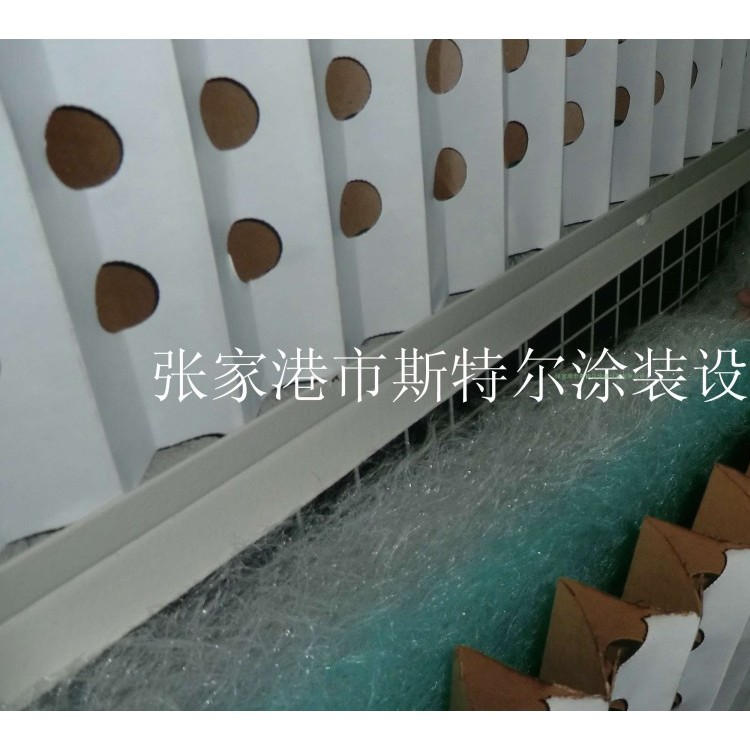
High-efficiency filtration material is chosen, with 600G precision-grade filter cotton laid flat on the galvanized mesh at the bottom of the static pressure chamber. It is then tightly secured with a round steel frame, achieving a secondary filtration of the air and ensuring a more uniform airflow into the workspace. This guarantees the uniformity of air volume and the cleanliness of the air. The filter cotton has a multi-layer structure, with an intermediate oil-impregnated layer that provides strong adhesion, ensuring air cleanliness with dust concentration ≯1.5mg/m³, dust particle count ≯200 per cm³, and large dust particles ≯5µm. Differential pressure gauges are set on the top and bottom of the filter cotton. An alarm is triggered when the filter cotton becomes severely clogged, significantly reducing the airflow speed and increasing the pressure difference, prompting a replacement. This prevents mismatched supply and exhaust airflows, which can cause excessive indoor-outdoor pressure differences and affect the painting effect. Its main technical specifications are:
Model: 600
Raw Resistance 19Pa
Final resistance 230 Pa
Average Capture Rate: 98%
Dust Holding Capacity: 419g/m²
Thickness: 25mm
Flame Retardancy - Meets F5 rating standard
2.4 Air Supply System: Composed mainly of an air blower, blower base, and steel frame. The blower bases are filled with sound-absorbing material to reduce noise and vibration.
Based on the workpiece characteristics, the empty wind speed in the paint room is above 0.23 m/s, calculations show that...
Q1=3600FV=3600×(14×10)×0.23=115920m3/h
Considering wind resistance and interference coefficients, a total air volume of 120,000 m³/h is selected, with a total of 4 groups of supply systems, and a total of 8 YDW-type centrifugal fans are configured.
Fan parameters are as follows:
Model: YDW
Airflow: 15,000 m³/h
RPM: 950 r/min
Pressure: 801 Pa
Power: 5.5 kW
Quantity: 8 units
2.5. Exhaust System: Comprised mainly of exhaust fans, ducts, and profiles, etc. During painting, to discharge the filtered air at high altitudes, two sets of exhaust systems are configured, each with a flow rate of 35,201 m³/h, to maintain the chamber in a slightly positive pressure state during painting, thereby ensuring the quality of the coating. Each set is equipped with one centrifugal fan, model 4-82.
2.6 Paint Mist and Waste Gas Treatment System: Utilizes dry treatment, with treated gases released into the atmosphere at high altitudes, in compliance with the national standard GB16297-1996.
Fan exhaust ducting