


Working Principle and Key Features
2. 1 Working Principle
The blow-off level gauge is mainly composed of three parts: the blowing device, a differential pressure (pressure) transmitter, and the blowing pipe circuit. A single-channel blowing device is suitable for measuring the level of atmospheric or open containers, while a dual-channel blowing device is suitable for measuring the level of pressurized containers.
The working principle of the blow molding level gauge is shown in Figure 2.1.

2.1 Working Principle of the Blowing Liquid Level Gauge
After filtering and减压, the gas enters the blowing device, where it is constantly bubbled out through the blowing tube, ending at the tube inserted into the medium being measured. Due to the very small gas flow exiting the blowing tube, the gas pressure at point A (PA) is equal to the pressure of the liquid medium, the gas pressure at point B (PB) is equal to PA plus the pressure difference DPAB between points A and B, and the gas pressure at point D (PD) is equal to the gas pressure at point C (PC) plus the pressure difference DPCD between points C and D. The liquid level height h of the container can be obtained by measuring the differential pressure DPBD between points B and D with a differential pressure transmitter.
PA-rgh=PC,
PB = PA + DPAB, which can be deduced to:
PB=PC+DPAB+rgh,
PD=PC+DPCD,
DPBD = rgh + DPAB - DPCD, where r is the liquid density and g is the local gravitational acceleration.
The pressure difference between points AB and CD is related to the pipeline distance between AB and flow rate. When designing the pressure tapping, try to minimize the distance between points AB.
The distance and flow rate to CD are consistent, thus DPAB = DPCD. Therefore, DPBD = rgh. By measuring DPBD, the liquid level height h inside the container can be calculated.
The blow-through level gauge can be understood as a non-contact liquid level measuring instrument, capable of measuring the liquid inside open or sealed containers. Apart from the air tube coming into contact with the medium being measured, neither the blowing device nor the measuring element of the differential pressure (pressure) transmitter comes into contact with the medium, thereby protecting the measuring element and reducing the maintenance of the instrument, increasing the reliability of measurement. Since the blowing device ensures a constant flow of gas output, the pressure measured by the differential pressure (pressure) transmitter automatically follows the change in pressure at the outlet of the air tube. Therefore, the output signal of the differential pressure (pressure) transmitter is proportional to the height of the liquid level in the medium.
The blow-down level gauge is not only suitable for measuring the level of clean liquids but is particularly adept at measuring the levels of corrosive acidic, alkaline, and saline liquids, thick liquids, crystalline liquids, high-temperature liquids, and liquids containing solid particles, as well as the levels of some fluidized bed materials.
2.2 Key Features
The liquid level measurement system composed of blow-off devices has no moving parts, and other measuring elements do not come into contact with the medium being measured, except for the blow-off pipe.
Single table installation, panel installation available with single, dual, or multi-way structure options.
Compact and sturdy, the main components required for measurement can be integrated onto a single panel, facilitating installation and maintenance.
All-mechanical structure, good sealing, low failure rate, and minimal maintenance required.
3 Key Technical Specifications
Measurement Accuracy: ±0.5% F.S.
Measurement Range: 0-250 kPa, corresponding to a water level height of 25 meters.
Response Time: 0.5 seconds.
PVC Pipe Length: 25 m.
Blow tube material: 304S.S., 316S.S., 316LS.S., PVC.
Process connection flange standard: HG/T 20592-2009, double-sided: DN80 PN40; single-sided: DN25 PN40.
Structural Styles: Single Table Mount, Single-Channel Panel Mount, Dual-Channel Panel Mount.
Gas Source Pressure: £0.8 MPa.
Power Supply: 24V DC.
Electrical Signal Output: 2-wire 4-20 mA DC or 2-wire 4-20 mA DC + HART communication protocol.
4 Dimensions drawing
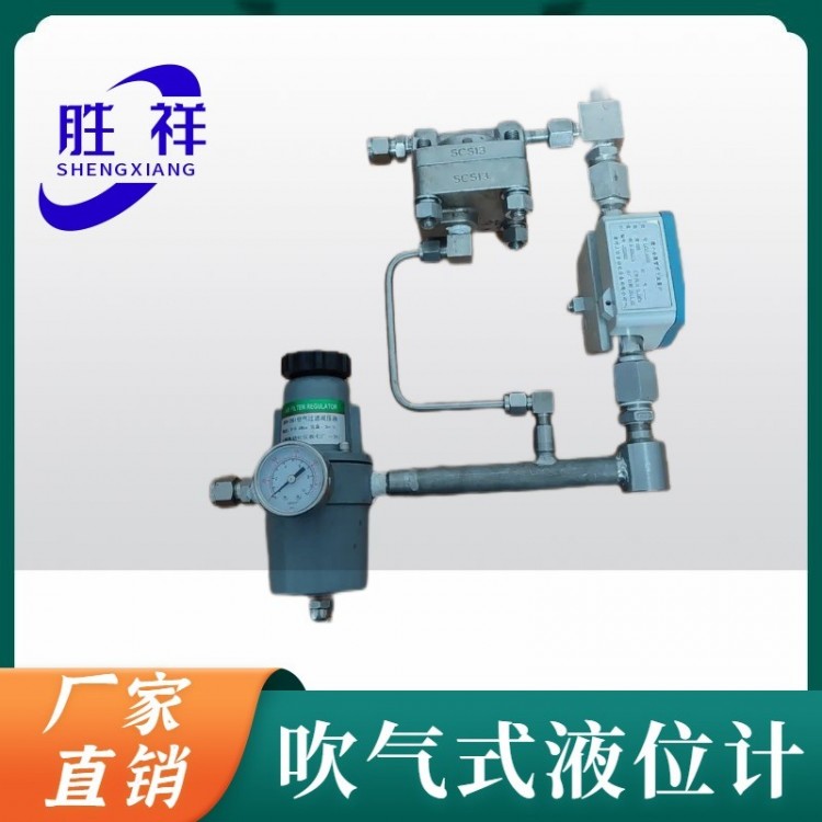
4.1 Installation Drawing of Blowing Device for Single Table

Image:
1. Filtered Pressure Relief Valve, 2. Pressure Gauge, 3. Pressure Regulator, 4. Flow Meter, 5. Flow Control Valve.
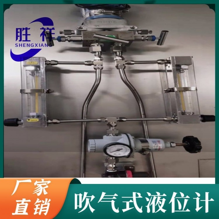
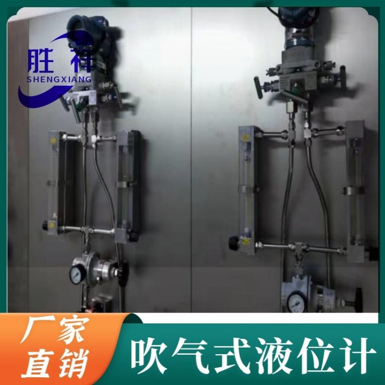
4.2 Panel Installation Single-Blow Device Outline Dimension Drawing

Image: 1 NPT 1/4-M20x1.5 Adapter, 2 Nut, 3 PTFE Gasket, 4 Welding Short Pipe

Image:
1. Inlet shut-off valve: Opens or closes the blow air source.
2 Gas Source Pressure Indicator Gauge: Gas Source Pressure Indication.
3 Pressure Relief Valve: Increases or decreases blowing pressure.
4. Inflate Flow Adjustment: Adjust the size of the inflate flow.
5 Blower Pressure Gauge: Indicates the blow pressure after the pressure reducing valve.
6. Export shut-off valve: Controls the gas flow to the blow pipe by opening or closing it.