


DN80 Coupling Bracket Price
Submersible pump coupling hook
Self-coupling hanger bracket
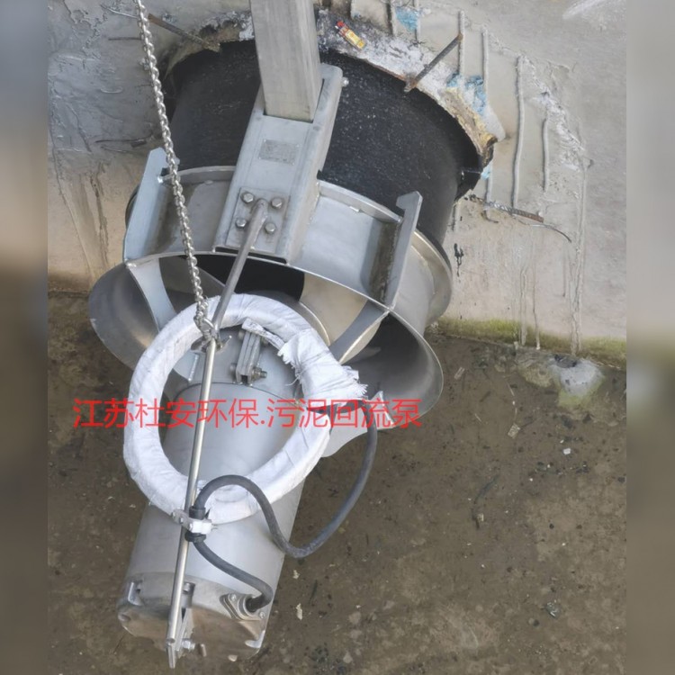
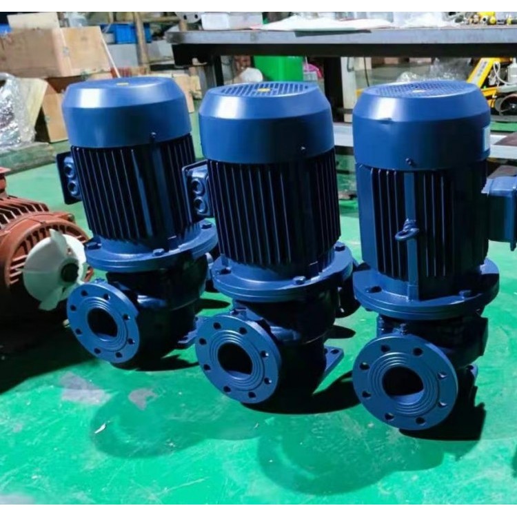
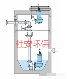
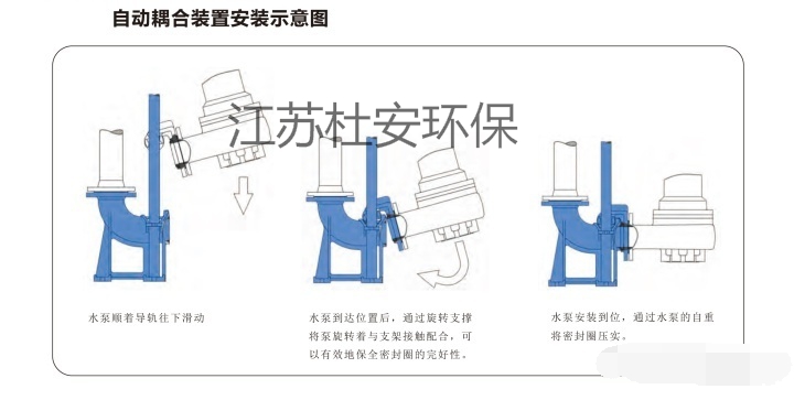
Submersible sewage pumps, after the installation of an automatic coupling device, are easy to install and maintain. Without an automatic coupling device, fixed installations require technicians to enter the water to unscrew bolts if the pump malfunctions, then lift the pump for repair, or use a smaller pump to remove water before entering for inspection. If the water quality is very poor, it can be difficult for a person to enter. This poses significant difficulties for maintenance. However, with the automatic coupling device of the GAK type submersible sewage pump, when it needs to be lifted, technicians do not need to enter the water to unscrew bolts; the pump can be directly lifted. After maintenance is completed, the pump can be sealed to the pipeline by sliding down the guide rail, ensuring normal operation. Small sewage pumps can be installed freely, while large models typically come with automatic coupling devices for easy installation and maintenance.
Stainless Steel Coupling Device | Stainless Steel Automatic Coupling Device | Submersible Pump Coupling | Sewage Pump Coupling Device
2. The automatic coupling device of the GAK type submersible sewage pump features a compact structure and minimal footprint. Due to its submersion in liquid, the pump can be directly installed in a sewage pool without the need for a separate pump house to house the pump and motor, thus saving considerable land and infrastructure costs.
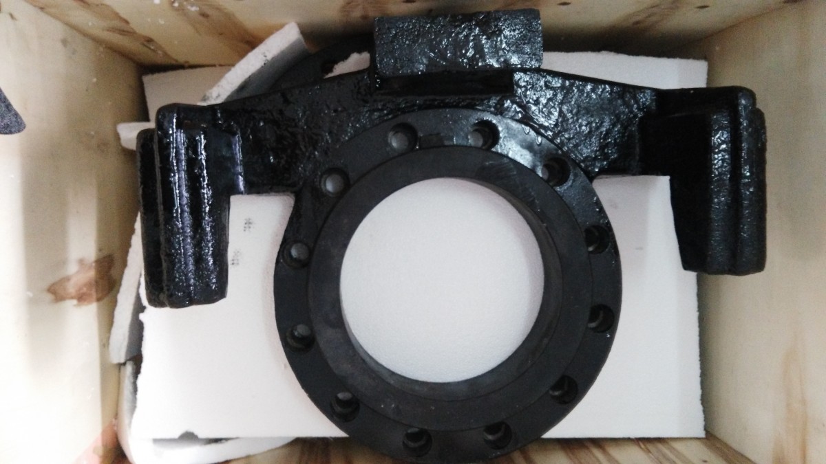
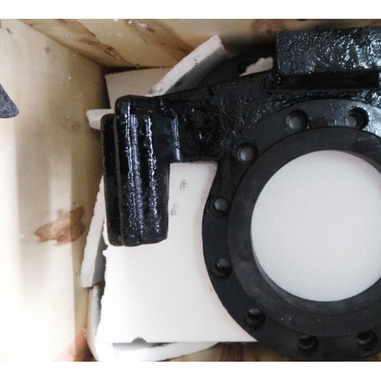
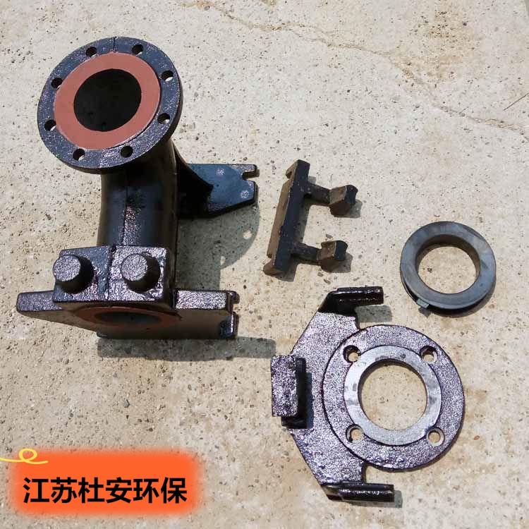
Composition of the automatic coupling device for GAK type submerged sewage pump:
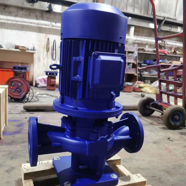
GAK Type Submersible Sewage Pump's Automatic Coupling Device, including coupler, coupling flange, guide rod, and upper fixed plate. The coupling base and sliding plate have annular grooves on their contact surface, with soft sealing gaskets securely fixed in the grooves. This structure ensures a tight seal between the sliding plate and the coupling base with the annular sealing grooves. Stainless Steel Coupling Device | Stainless Steel Automatic Coupling Device | Submersible Pump Coupling | Sewage Pump Coupling Device
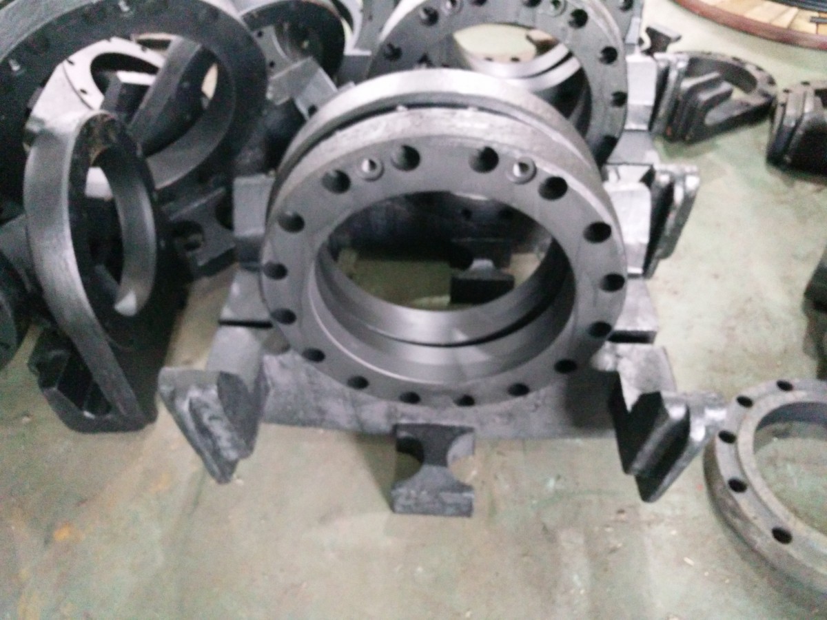
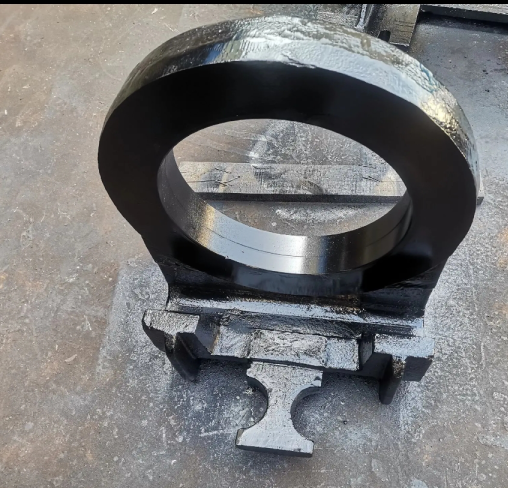
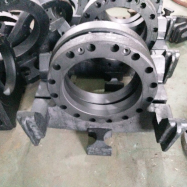
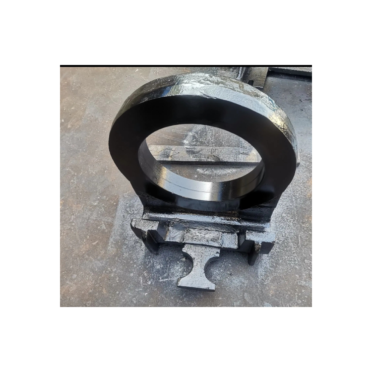
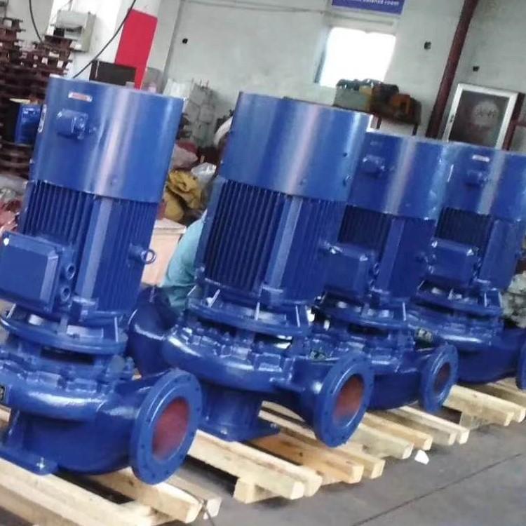
The GAK80 Submersible Sewage Pump features an automatic coupling device. Depending on the application environment, our company has developed cast iron and stainless steel automatic coupling devices for submersible sewage pumps. The automatic coupling device guides can also be customized to be welded pipe, seamless steel pipe, or stainless steel pipe.
Jiangsu environmental protection configuration cast iron type automatic coupling devices include the following types:
GAK50 Submersible Sewage Pump Automatic Coupling Device (Cast Iron)
GAK65 Submersible Sewage Pump Automatic Coupling Device (Cast Iron)
GAK80 Submersible Sewage Pump's Automatic Coupling Device (Cast Iron)
GAK100 Submersible Sewage Pump Automatic Coupling Device (Cast Iron)
GAK150 Submersible Sewage Pump Automatic Coupling Device (Cast Iron)
GAK200 Submersible Sewage Pump Automatic Coupling Device (Cast Iron)
GAK250 Automatic Coupling Device for Submersible Sewage Pumps (Cast Iron)
GAK300 Submersible Sewage Pump Automatic Coupling Device (Cast Iron)
GAK350 Submersible Sewage Pump's Automatic Coupling Device (Cast Iron)
GAK400 Submersible Sewage Pump Automatic Coupling Device (Cast Iron)
GAK450 Submersible Sewage Pump Automatic Coupling Device (Cast Iron)
GAK500 Submersible Sewage Pump's Automatic Coupling Device (Cast Iron)
GAK600 Submersible Sewage Pump Automatic Coupling Device (Cast Iron)
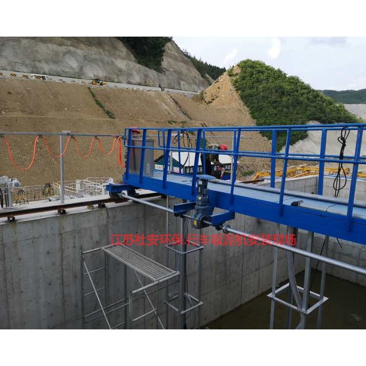
Installation Instructions for Submersible Pump Automatic Coupling Device:
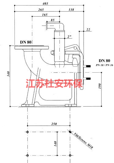
This description applies to the wet installation method of submersible pumps. (Please refer to the "Axial Diagram of Automatic Coupling Device" for the following part numbers.)
A. Pre-treatment before the installation process. Note: Process A is required for DN200~DN500. No process is needed for DN50~DN150.
1. The position of the base (11) foot bolt holes.
Prior to the concrete pouring in the sewage pond, ensure the foot bolt holes for the base (11) are pre-drilled. The center of the pre-drilled holes aligns with the Z-axis of the installation system as per the base fixing bolt layout (refer to Table 1), with the size of the pre-drilled holes being 100*100 square holes.
2. Further核准the Z-axis with the center of the wall-out pipe, as well as the centerline of the foot bolt pre-drilled holes and the centerline of the pool mouth support block, should all lie within the same axis plane. The dimensions must comply with the installation system diagram requirements before pouring can proceed.
B. Installation Process
1. Determine the position of the bearing block (2)
Draw a vertical line on the pool outlet wall adjacent to the drainage pipe, ensuring the line is within the plane of the center of the drainage pipe. This vertical line serves as the symmetrical installation line for the support block (2).
2. Install support block (2)
Align the centerline of the support block (2) with the installation reference line at the pool opening. Drill two holes at the center of the pool wall according to the slot distance of the support block (2), referencing the size of the expansion bolts. Insert the expansion bolts (1) to secure the support block (2), but do not tighten them completely.
3 - a base mounting (DN50~DN150)
3.1 - a Confirm the correct position of the base, place the base at the bottom of the pool. Attach a plumb line to the self-supporting block (2) to align it with the centerline of the support block (2). Use the plumb line to align the centerline of the base (11) and ensure that the centers of the two cones on the support block (2) and the two cones on the base (11) are on the same plumb level. Mark the position of the base (11)'s foot bolt holes.
3.2 - a Base Support (11) Footbolt Holes: Remove the base support (11), drill holes directly at the marked positions according to the size of the expansion bolt (12), clean the debris from the holes, place the base support (11) back, insert the bolt (12), and tighten it.
3 - Base Mount (DN200~DN500)
3.1b - Correct installation position of the base (11): Place the base (11) at the bottom of the pool. Hang a plumb line from the self-supporting block (2) so that it aligns with the centerline of the block (2); locate the centerline of the base (11) using the plumb line, and ensure that the centers of the two cones on the self-supporting block (2) and the two cones on the base (11) are in the same vertical line. Adjust the position of the anchor bolts in the pre-drilled holes.
3.2 - b Drilled holes for pouring; fill the holes with concrete, ensuring the position of the anchor bolts within the holes and the length of the bolts extending above the ground. Recheck the installation dimensions of the anchor bolts after the pouring is complete.
After casting, the curing period is 15 days (note: high-quality concrete and sufficient footer base thickness are essential conditions for the pump to operate vibration-free).