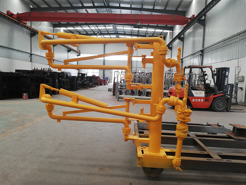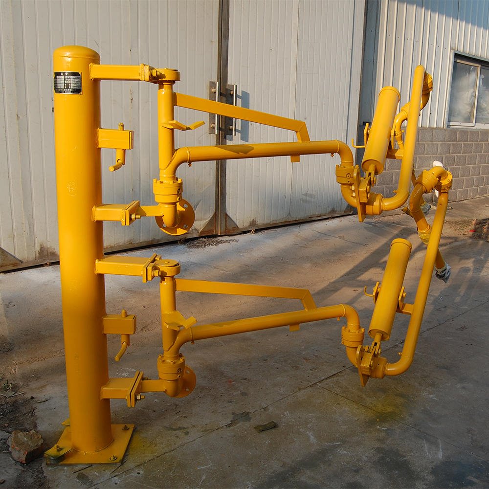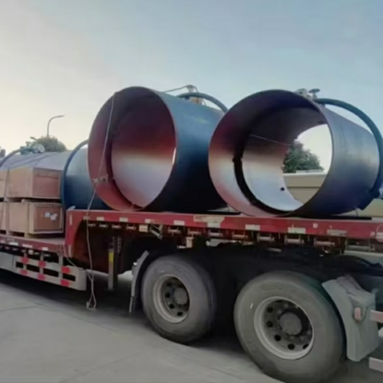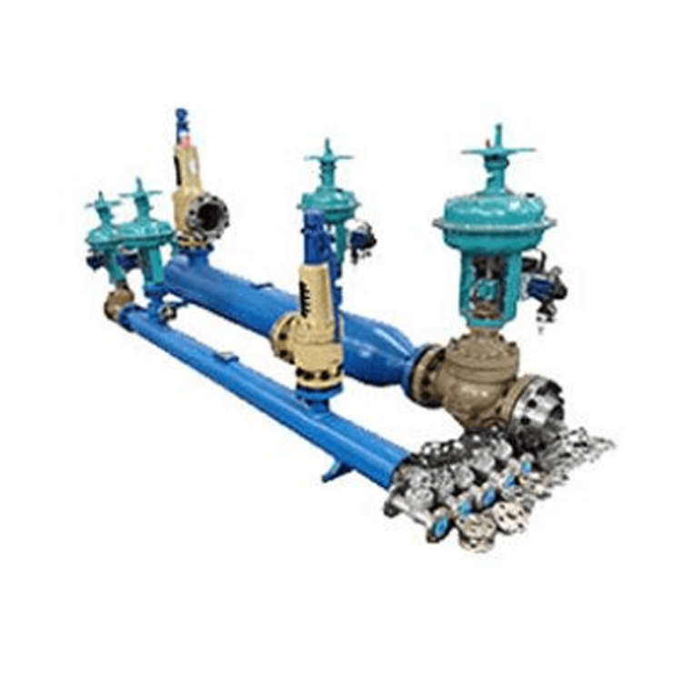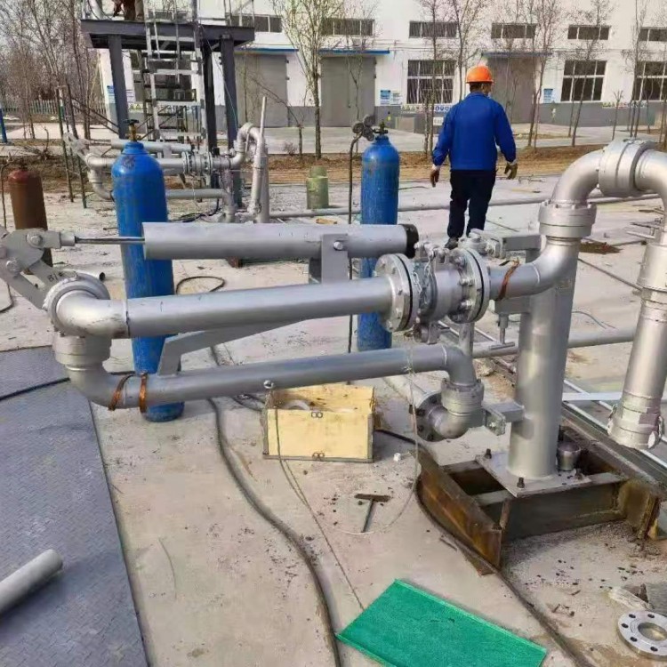

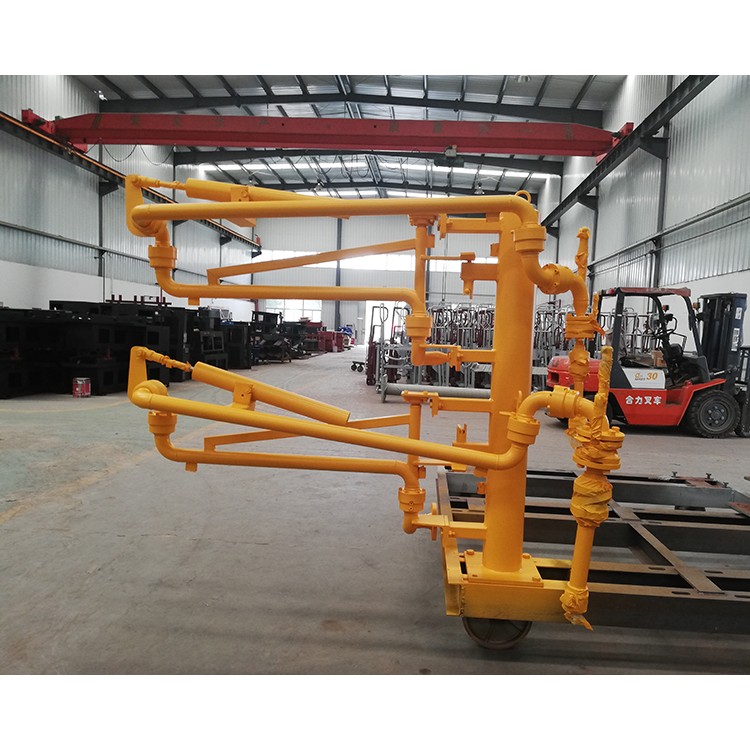

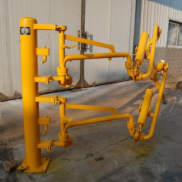


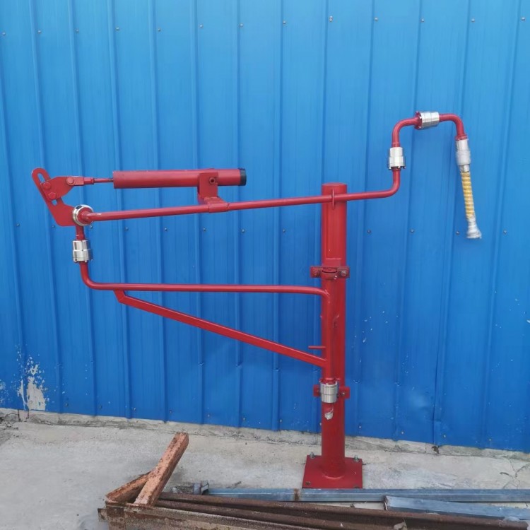
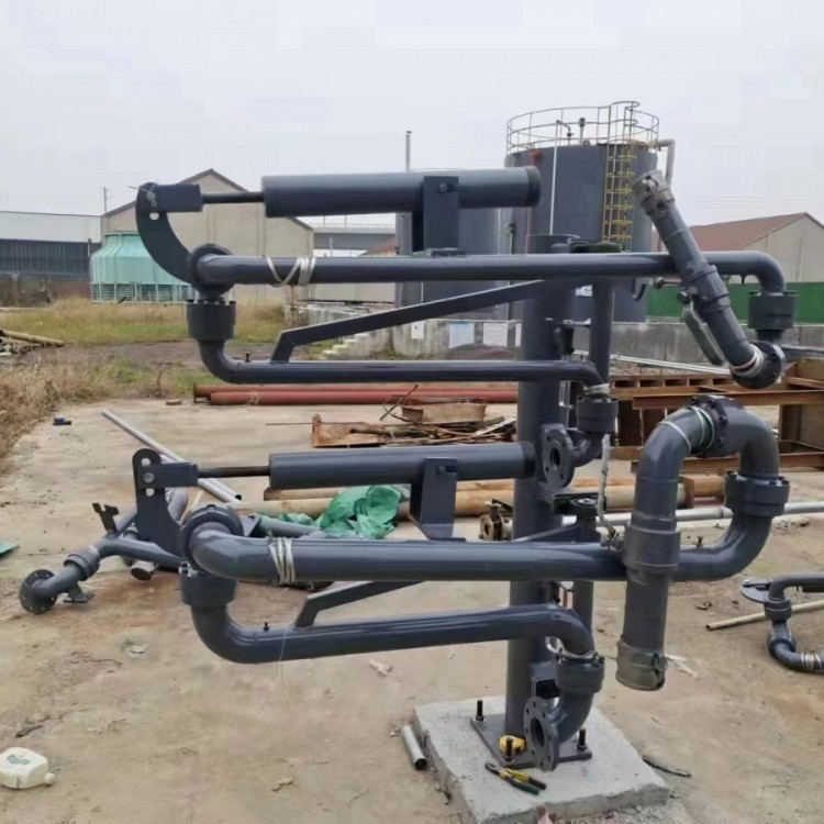

Herringbone pipes, also known as liquid loading and unloading arms, are composed of rotating joints, inner arms, outer arms, vertical pipes (for land use), three-axis joints (for marine use), balancers, control systems, and other components. They are primarily used as loading and unloading equipment for liquid media in tanker trucks, train tankers, or tank ships.
Hawk pipe features:
1. Compared to the traditional flexible hose connections, the鹤pipe uses a rigid connection method, enhanced by safety features such as quick disconnects, effectively preventing burst or breakage incidents, offering a high degree of reliability.
2. The rotating unions are made with superior double-roll track technology, offering easy 360-degree rotation, zero leakage, and convenient maintenance.
3. The flexible, balance spring cylinder balancer with adjustable balance ensures easy and effortless operation of the loading and unloading arm. It allows a single person to easily connect pipes to tank trucks and effortlessly control the loading and unloading process.
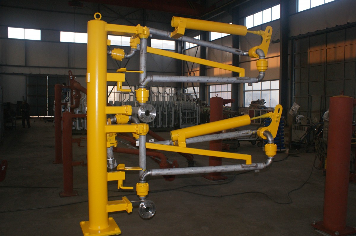
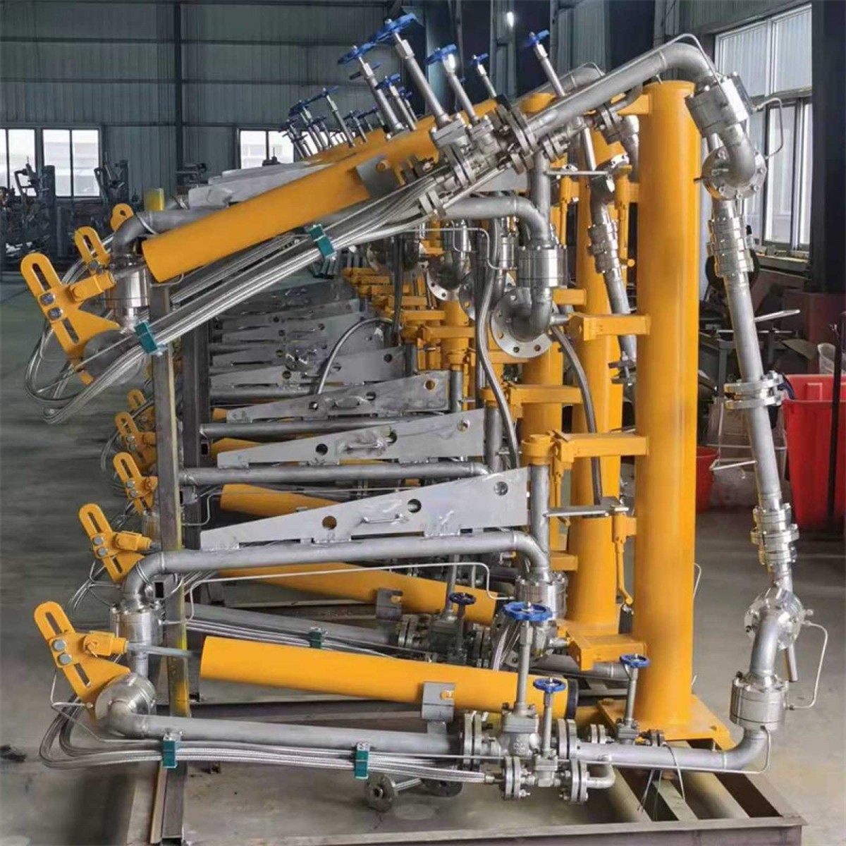
4. Customized dimensions based on the customer's loading and unloading range requirements; during the process, the tank truck moves synchronously within the normal range of the tank truck's movement.
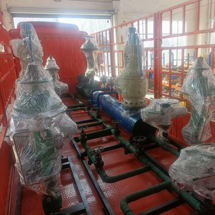
5. Pipelines are made of materials such as carbon steel, stainless steel, and aluminum alloy, depending on the type of liquid medium, ensuring a long service life.
6. The pipeline can be lined with PTFE and equipped with a heating system, capable of transporting various liquid mediums such as hydrochloric acid and asphalt.
7. Utilizing sealed loading and unloading procedures can minimize the volatilization of the medium, thereby reducing environmental pollution.
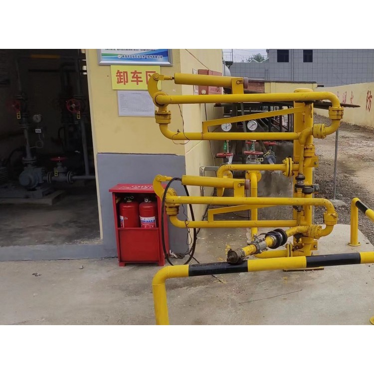
The installation principle of the crane pipe:
1. Necessary safety measures should be taken during installation to prevent accidents and ensure the safety of personnel and equipment.
2. The connection point between the pier and the crane pipe should be equipped with a standard flange corresponding to the crane pipe, with the flange located approximately 3.7 to 4.0 meters from the track surface.
3. Assemble by referring to the work drawing, install from the base rotary to the vertical aluminum tube, from bottom to top, and then mount the balancer.
4. When installing the balancer, first raise the oil feeding arm to about 60°, install the pins on both sides of the balancer onto the hooks, then align the single ear of the lifting lever on one end of the balancer with the single ear of the rotating shell, install the pins, and finally, install the open pins.
5. When adjusting the balancing force, place the oil pump in a horizontal position, unscrew the end cover of the balancer, and you will see the adjusting screw. When the crane pipe tends to drop freely, tighten the screw with a socket wrench. When the crane pipe tends to rise, loosen the screw until the oil feed arm stabilizes between -5° to 60°.