
Technical Brief for Fire-Resistant Wire Bridge Support
1.1 Metal cable trays and their supports, as well as metal cable conduits for introduction or extraction, must be reliably grounded (PE) or bonded to neutral (PEN) and comply with the following regulations:
The entire length of the metal cable tray and its supports should be connected to the grounding (PE) or neutral (PEN) main at least 2 times.
b. The ends of the non-galvanized cable bridge connecting plates are cross-connected with grounding wires, with the minimum allowable cross-sectional area of the grounding wire not less than 4 mm².
c. The ends of the galvanized cable bridge connecting plates do not span across the grounding wire, but the connecting plates have at least 2 connection bolts with anti-loosening nuts or washers.
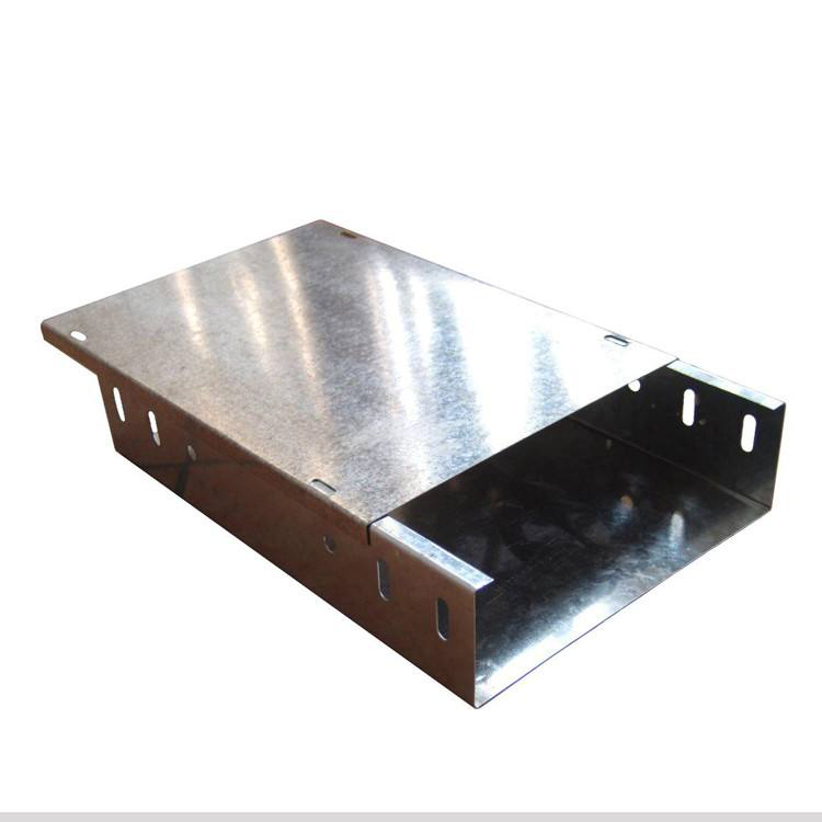
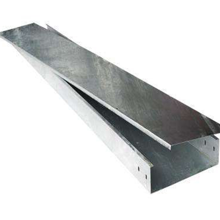
2.1 Cable tray installation shall comply with the following regulations:
a. Steel cable trays exceeding 30m in length, and aluminum alloy or glass fiber reinforced plastic cable trays exceeding 15m in length, are equipped with expansion joints; compensating devices are installed at the transition of building deformation joints where the cable trays cross.
b. The bend radius at the turn of the cable tray shall not be less than the minimum allowable bend radius for cables inside the tray. The minimum allowable bend radius for cables is listed in the following table.
Cable minimum bend radius
c. When no design specifications are provided, the spacing between supports for horizontally installed cable trays should be 1.5-3m, and for vertically installed, not more than 2m.
d. Bolts between bridge and bracket, and bolts for bridge connection plates are securely fastened without any omissions; nuts are located on the outer side of the bridge. When aluminum alloy bridges are fixed to steel brackets, there are anti-electrolytic corrosion measures with mutual insulation.
e. Cable trays are installed below flammable and explosive gas pipelines and thermal pipelines. In the absence of design requirements, the minimum clear distance from the pipelines shall comply with the specifications in the following table:
Minimum Net Distance to Pipe (m)
f. Bridgeways installed within vertical shafts and crossing different fire-resistant zones are equipped with fireproofing measures in accordance with design specifications.
g. When welding the bracket to the embedded parts, ensure full welds; for expansion bolt fixation, use compatible bolts, secure the connection tightly, and ensure all anti-loosening parts are in place.
2.2 Cable starting, ending, and branching points should be marked with signage.
2.3 Cable laying within the bridge should comply with the following regulations:
Cables laid at an angle greater than 45 degrees should have a fixed point every 2 meters.
b. Perform sealing treatments at cable entry and exit points in cable trenches, shafts, buildings, cabinets (panels), desks, and at pipe openings.
c. Cable laying is strictly prohibited from having defects such as twisting, armor flattening, sheath breakage, and severe surface scratches.
d. Cables are laid neatly with fixed points at both ends, at bends, and every 5-10m along the horizontal cable runs. The spacing of cable fixations within vertical bridge channels should not exceed the specifications in the following table. Cable fixation spacing (mm).
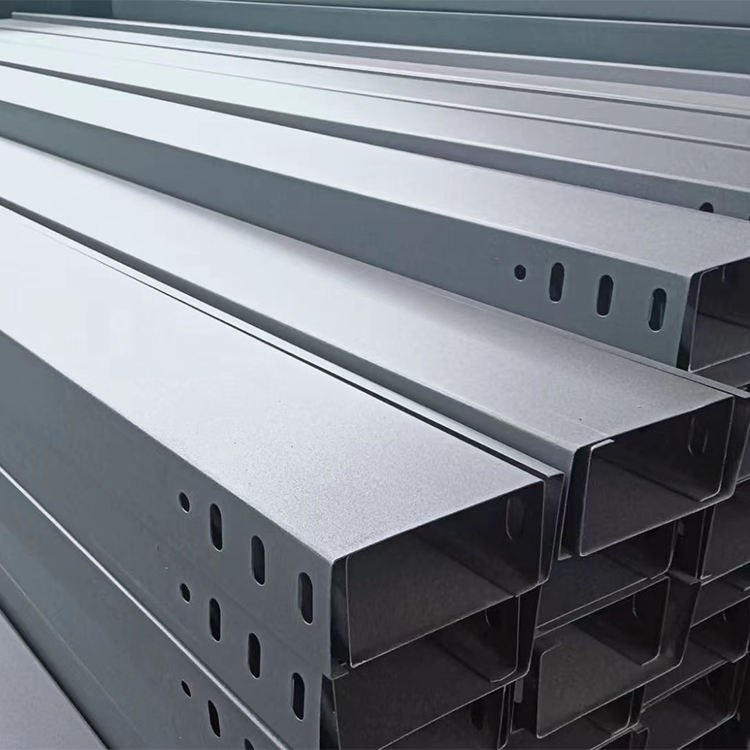
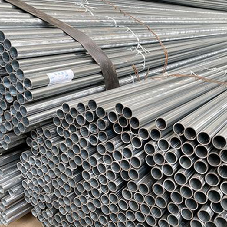
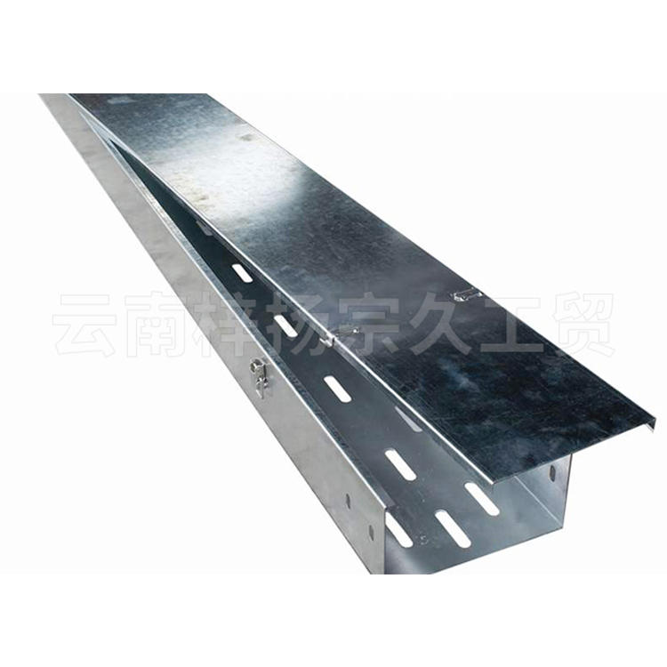
Yunnan Ziyang Zongjiu Industry & Trade Co., Ltd. is a cable tray manufacturer in Yunnan, specializing in tray production and processing for many years. We offer standard specifications and factory prices, with galvanized, fire-resistant, and installed trays. If you need to purchase cable trays, please feel free to call for detailed discussions!!