


Description:
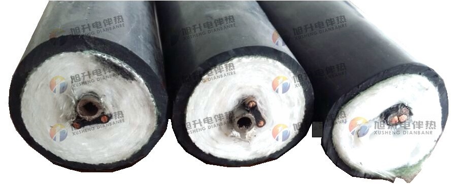
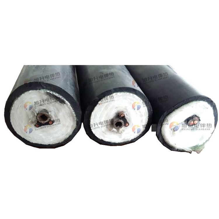
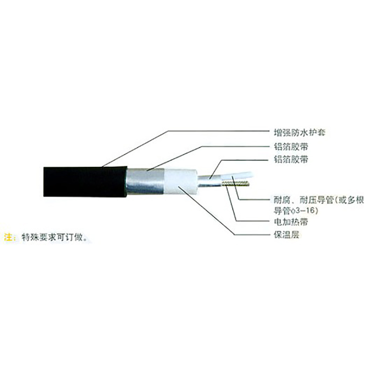
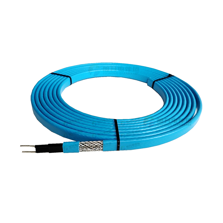
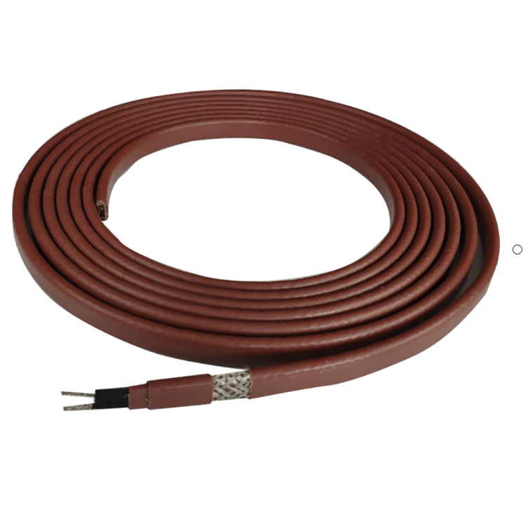
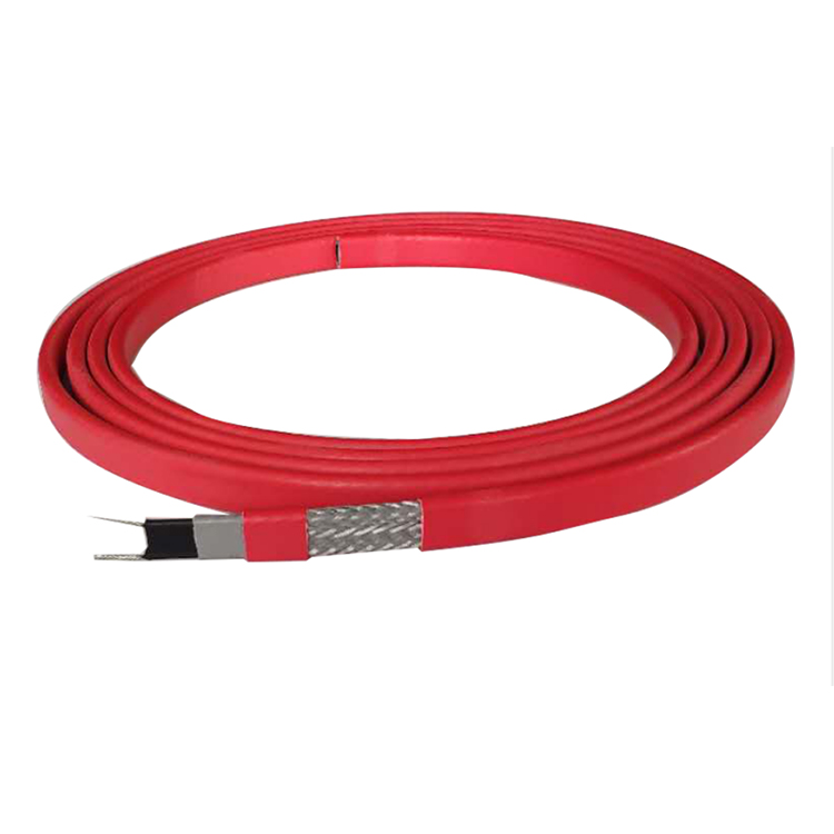
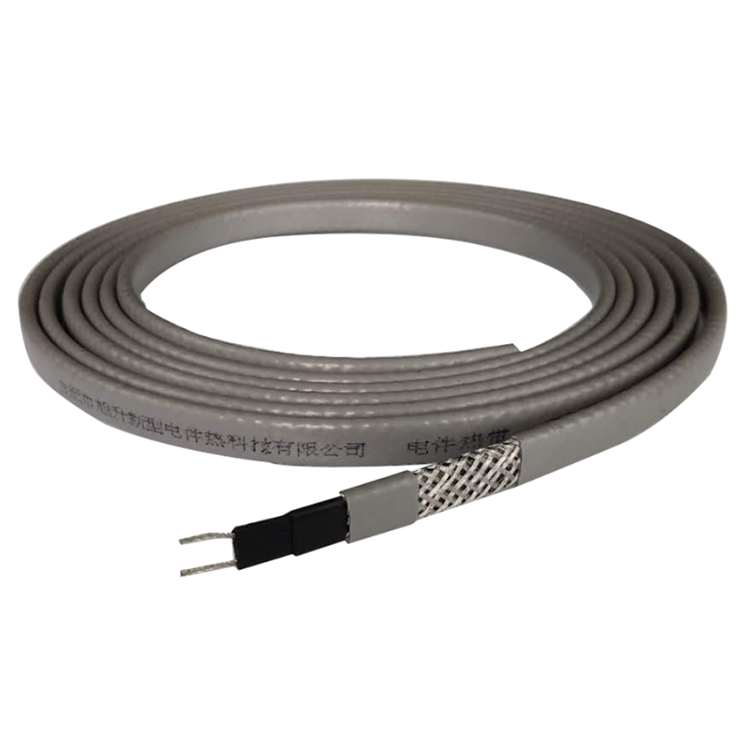
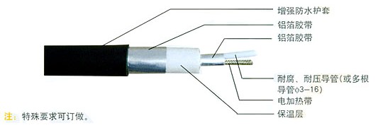
Corrosion-resistant heating sampling composite pipes are an important component in environmental monitoring systems. They are composed of an inner core made from a set of corrosion-resistant high-performance resin tubes, supplemented by self-limiting temperature heating cables and compensating cables, encased in an insulating layer, and finally coated with a flame-retardant polyethylene (PE) protective sheath. The automatic temperature-limiting function of the self-limiting temperature heating cables ensures that a certain temperature is maintained within the sampling tube, thus as closely as possible keeping the collected sample consistent with the initial value, ensuring the continuous and accurate collection of gas samples by the environmental monitoring system. Depending on the actual composition and temperature of the collected gas samples, the sampling tubes within the corrosion-resistant heating sampling composite pipes can be made of different materials such as PFA (polytetrafluoroethylene and perfluoroalkylether copolymer), FEP (polytetrafluoroethylene and hexafluoropropylene copolymer), PVDF (polyvinylidene fluoride), PE (flame-retardant polyethylene), nylon 610, etc. The heating cables can be chosen in medium, low, or high temperature variants, and additional compensation wires, power cables, etc., can be added according to customer requirements. The product has a service life of over 15 years.
The Corrosion-Resistant Heating Sampling Composite Pipe is a composite assembly made up of various components, combining multiple systems within a limited cross-sectional area.
● Sampling System: Combinable with various types and materials of sampling tubes: Teflon PFA, FEP, PE, Nylon 610, 12, Copper Tube, 316SS, 304SS, etc.
● Thermal System: High-efficient insulation, flame-retardant, and lightweight thermal insulation; automatic temperature-limiting heating cables or constant power heating cables.
● Electrical System: Equipped with instrument signal cables, compensation cables, and control cables to meet the requirements for instrument display and monitoring.
● Safety System: Adaptable to various process conditions, systems are shielded and isolated using aluminum foil or metal mesh, achieving fire safety, static electricity prevention, and electromagnetic shielding. Some include waterproofing film and protective sleeves with enhanced flame retardancy and UV protection. The combination of multi-systems integrates multiple functions into one, simplifying complex engineering. It provides excellent support for remote work and system remote diagnostics. The heating system prevents condensation of gas inside the pipes, maintaining measurements above the dew point, ensuring measurement accuracy. It creates conditions for centralized computerized control. The reinforced outer sheath prevents cross-contamination and damage due to other factors.
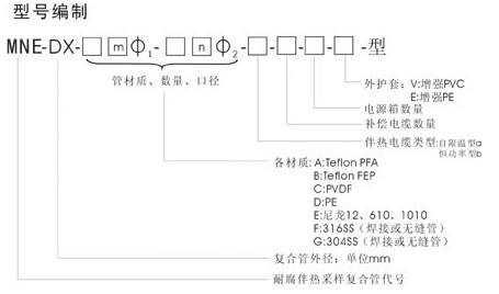
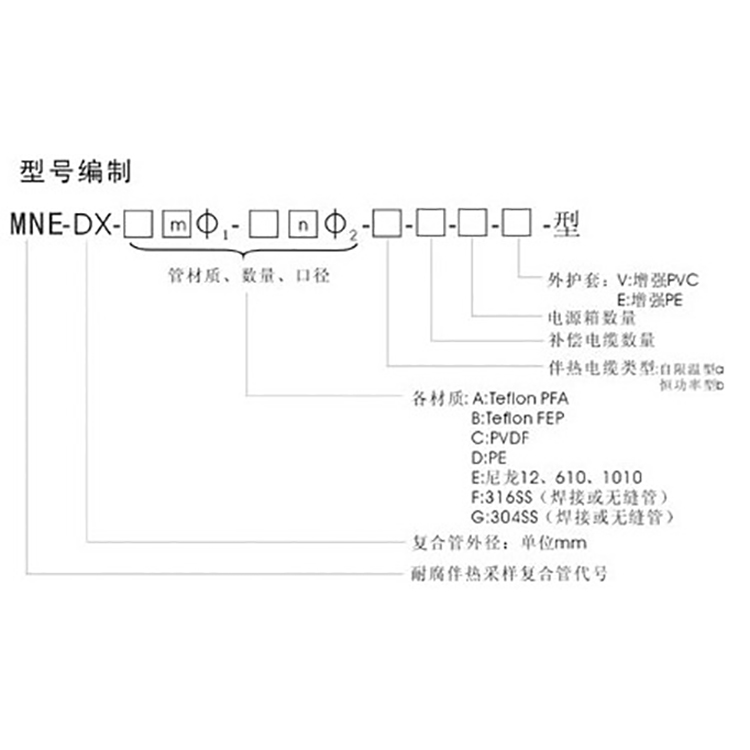
Typical Model Introduction
MNE-D45-B3Φ9.5-2Φ6.5-a-1-3-Type E
Equation: MNE-Corrosion-resistant Heating Sampling Composite Pipe
D45 - Outer Diameter of Composite Pipe
B3Φ9.5-2-Φ6.5 — 3 tubes Φ9.5 and 2 tubes Φ6.5 made of Teflon FEP
a - Self-limiting heating cable
1 - Instrument Compensation Cable, 1 pc
3 - Power Cables, 3 Pieces
E- Outer Sheath Material: Reinforced Polyethylene
Product Technical Specifications
1. Electrical Specifications
(1) Standard power of constant power electric heating tape: 40W/m
(2) Rated Voltage: 220V
(3) Maximum heating length: 100-130m
(4) Temperature Controller Must Be Provided
(5) Equipped with residual current protection device
2. Thermal performance specifications
At -10°C ambient temperature and a wind speed of 10 m/s, the temperature inside the pipe can be maintained between 40-160°C.
(2) Sampling tubes are resistant to corrosion from various acidic and alkaline mediums, with a pressure resistance of 0.6 Mpa and no leakage.
(3) Sampling tubes can operate continuously at temperatures up to <250 degrees Celsius.
3. Installation Specifications
(1) Composite pipe with a minimum bend radius of 0.5m
(2) Continuous Length: 100-130m
(3) Smaller fixed distance: 5m vertically, 2m horizontally
Note: Do not twist or drag on the ground during installation; the tube head sleeve is only to be removed during the installation of the junction point.