


I. Circuit Principle:
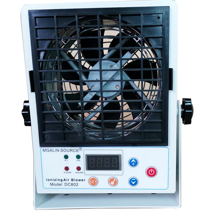
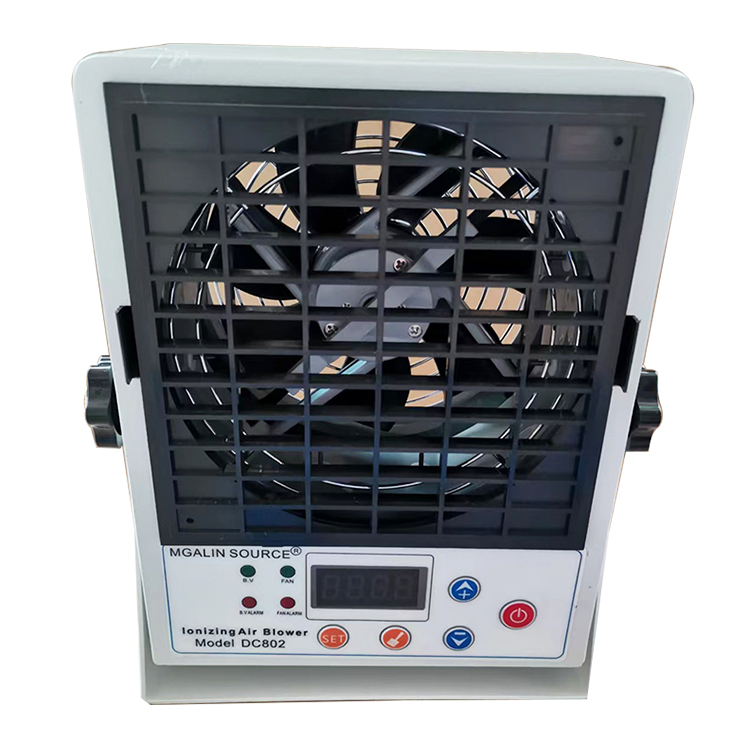
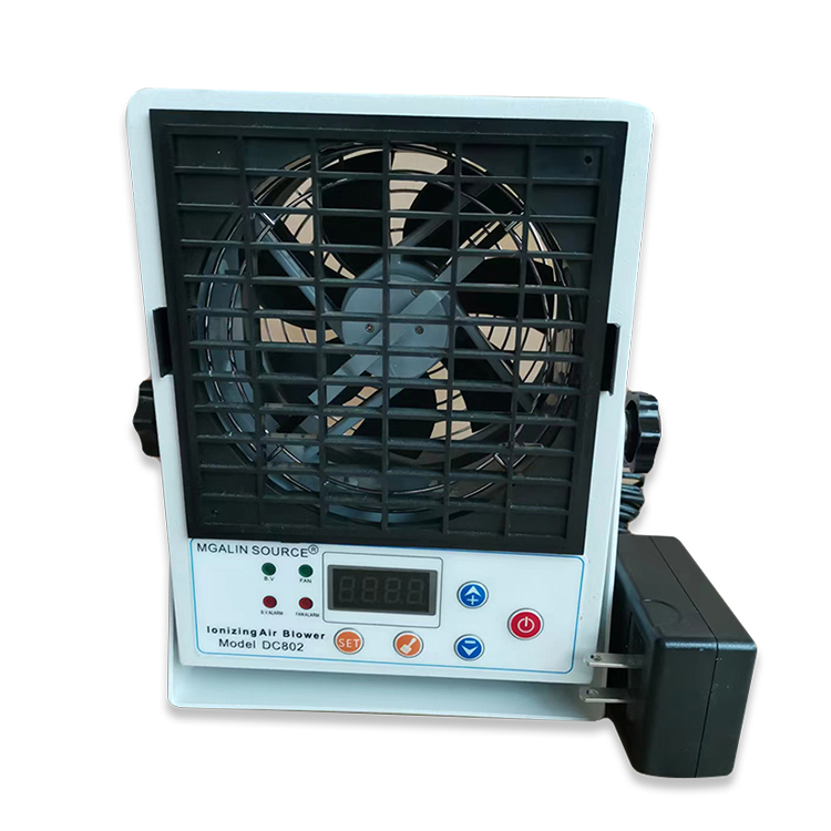
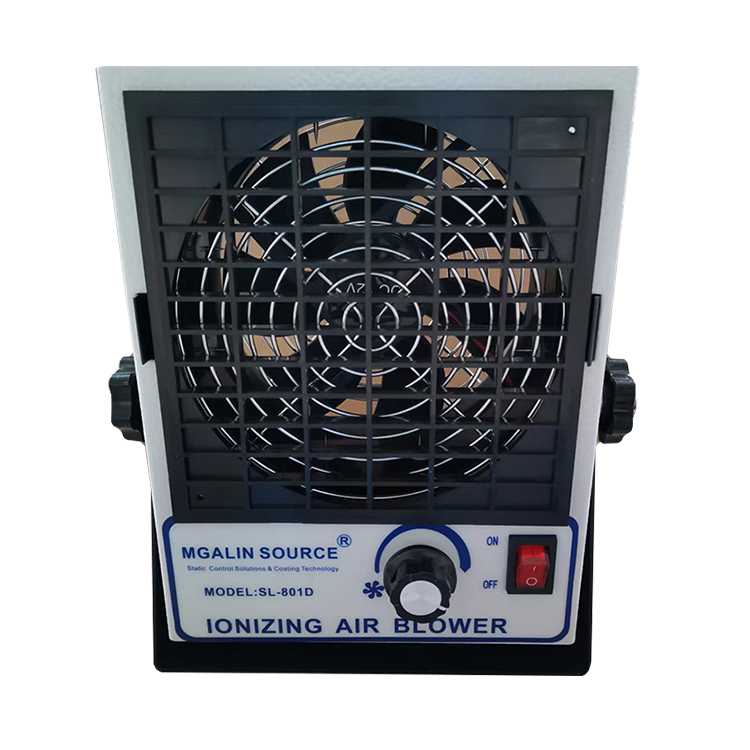
The MGALIN DC ion blower utilizes an internationally certified detection and control circuit. The detection circuit automatically adjusts the positive and negative ion output based on the ion level voltage at the sensor port of the blower's exhaust outlet, ensuring excellent static electricity removal performance.
Section 2: Circuit Diagram Illustration

Section 3: Instructions for Use
Press and hold the set button to enter parameter settings.
1. Balanced Voltage Parameter Setting:
1) Set the balanced voltage with the voltage setting button. Press and hold to display 1-50. 1 indicates the function is to set the balanced voltage parameters, and 50 indicates the voltage value is ±50V.
2) Press the shift key and select the units or tens digit.
3) Set parameters by pressing the up or down arrow keys, with a range of ±99V.
4) If no other function parameters need to be set, press and hold the Set button to exit. If other function parameters need to be set, press the Set button again. Proceed to the next function setting.
2. Automatic cleaning interval setting:
1) Press and hold the set key to enter the function settings, then press the set key again to display 2-05. The "05" indicates an automatic cleaning interval of every 5 hours.
2) Press the shift key and select the units or tens digit.
3) Adjust parameters by pressing the up or down arrow keys, with a range of 23 hours.
4) If no other function parameters need to be set, press and hold the setup to exit. If other function parameters need to be set, press the setup button again. Enter the next function setup.
3. Automatic Cleaning Cycle Parameter Setting:
1) Press and hold the set button to enter the function settings, then press the set button again to display 3-05, where 05 indicates cleaning 5 times.
2) Set parameters by pressing the up or down arrow keys, with a range of 5 adjustments.
3) If no additional function parameters need to be set, press and hold the Set button to exit. If additional function parameters need to be set, press the Set button again. Enter the next function setup.
4. Beeper switch parameter settings:
1) Press and hold the set key to enter the function setting, then press the set key again to display 7-01, where 01 indicates on.
2) Set parameters by pressing the up or down arrow keys; the range is from 0 to 1.
3) If no other function parameters need to be set, hold the set button to exit. If other function parameters need to be set, press the set button again. Enter the next function setup.
5. Balanced Voltage Calibration Parameter Settings:
1) Press and hold the set key to enter function settings, press the set key until it displays 5500. If the calibration instrument shows a positive balanced voltage, such as +20V, press the up key to adjust, making the instrument display within 10V. If the calibration instrument shows a negative balanced voltage, such as -20V, press the down key to adjust, making the instrument display within 10V. Then, press and hold the set key to exit.
2) If no other function parameters need to be set, hold down the set button to exit. If other function parameters need to be set, press the set button again. Enter the next function setup.
6. Fan Speed Parameter Settings:
Fan speed has 6 levels, F-01 where '01' denotes level 1. Adjust the speed by pressing the up or down arrow keys.
7. Manual Cleaning:
Press and hold the Clean button to enter Clean mode.
8. Keyboard Lock and Unlock Settings:
1) Press and hold the Set key and the Up key to enter keyboard lock, display -OFF.
2) Press and hold the Set key and the Down key to unlock the keyboard, display shows 0000. Press the Shift key and either the Up or Down key, input 1234, display shows ON. Then press the Set key again to unlock the keyboard.