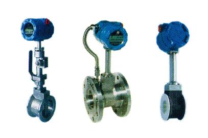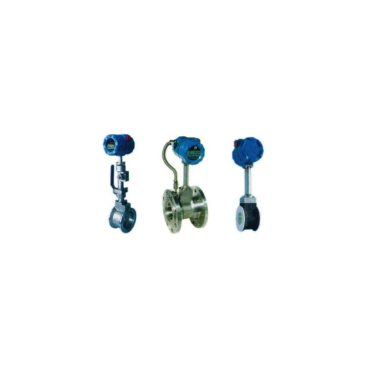


Capacitive Turbine Flow Meter
Description:
Piezoelectric Turbulence Flow Meter
CN321A Type Capacitive
CN321B Piezoelectric Model
The probe of a capacitive vortex shedding flow sensor is composed of a pair of differential capacitors. The alternating vortex forces generated by the vortex generator act on both sides of the probe, causing differential capacitance changes inside the probe, which are then converted into flow pulse signals by an amplifier. The unique internal structure provides the probe with excellent vibration resistance and the ability to measure lower flow rates. The base material of the probe's capacitor plates is formed at over a thousand degrees Celsius using imported ceramics, thus offering excellent high-temperature resistance. The process and structure of the core components are fundamentally different from those of detection elements at home and abroad, ensuring high reliability. The intelligent sensor is versatile for both gas and liquid, with an automatic frequency band tracking feature, eliminating the need for potentiometers or toggle switches to adjust the frequency band and sensitivity. It has no zero drift, allows for free range setting, and truly achieves on-site no-tuning. This circuit inhibits different vibration frequencies, enhances vibration resistance, and has linearization functions, with overall performance superior to similar products at home and abroad. If the designed flow deviates significantly from the actual operating flow, it may prevent the flow meter from operating normally. In most cases, the CN321 can replace the same specification of a vortex shedding flow sensor with a nozzle without changing the pipeline.
Features:
Wide operating temperature range
·Excellent vibration resistance
· Low minimum flow rate
· Broader Range
·Full specifications
High precision
Installation Requirements
·Sensors should be installed horizontally or vertically (fluid flow from bottom to top) on the pipe corresponding to the nominal diameter.
·A certain length of straight pipe section should be configured upstream and downstream of the sensor, with the length meeting the requirements specified in the table below.
·Flow control valves should not be installed on the upstream side of the sensor.
·If the length of the upstream straight section does not meet the requirements, it is recommended that a fluid straightener be installed in the upstream pipeline.
·Do not install sensors on pipes with intense vibration to avoid affecting accuracy. If installation and use on vibrating pipes are necessary, take the following measures to minimize the interference caused by vibration.
1. Install fixed support points at the upstream 2D of the sensor.
2. Overinstall flexible hoses while meeting the requirements for the straight section.
·When installing the sensor on a high-temperature pipeline, the transmitter must be vertically mounted downwards.