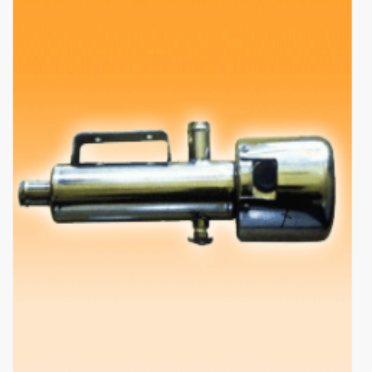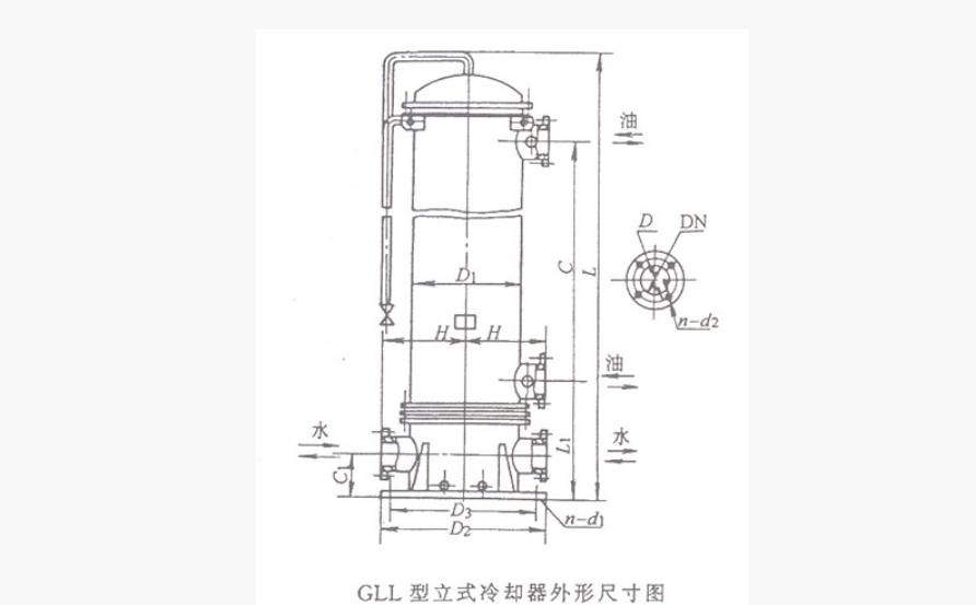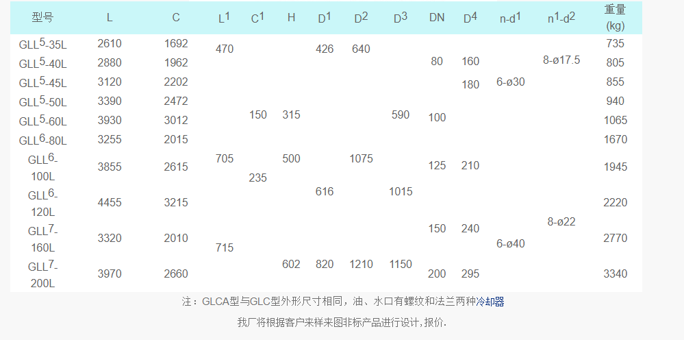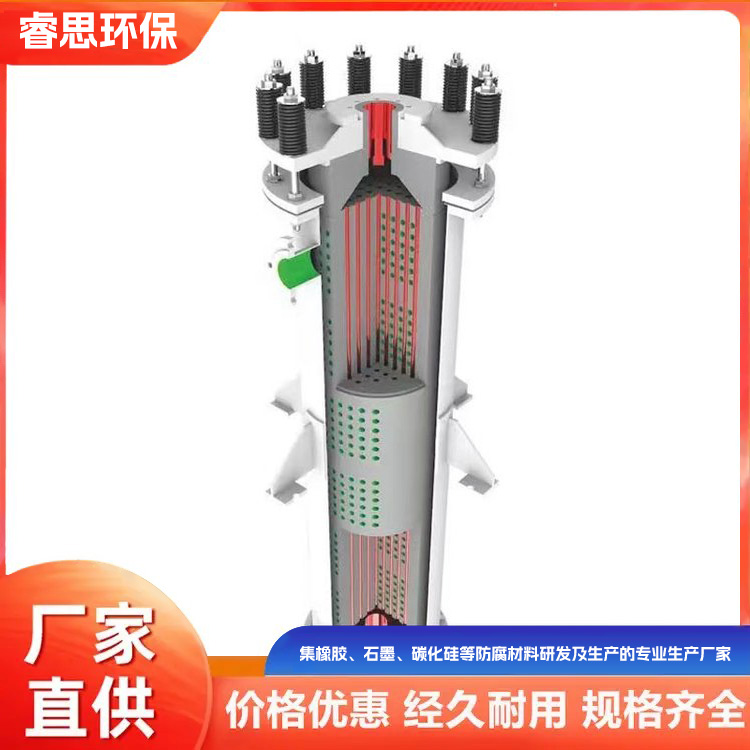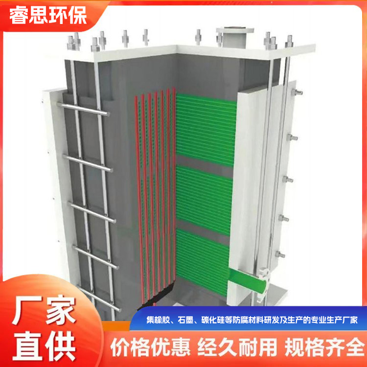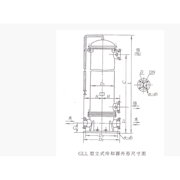
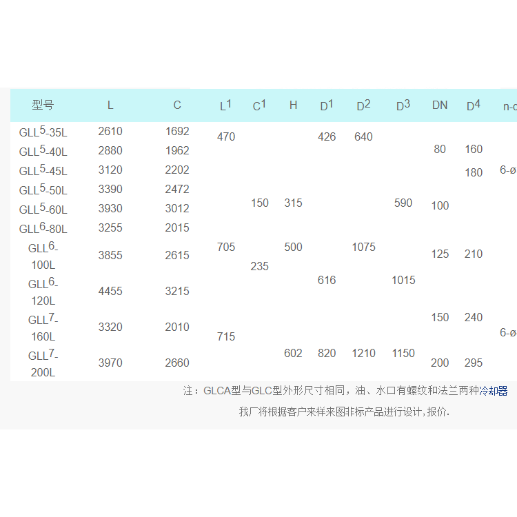


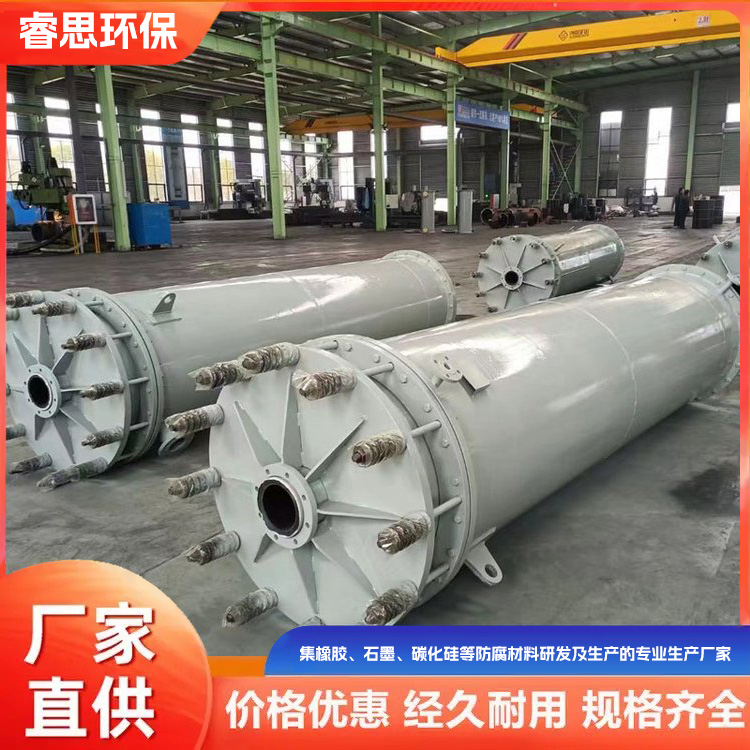


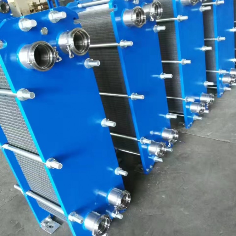
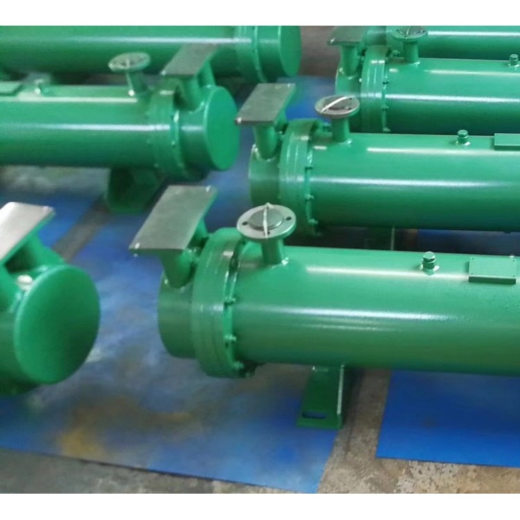

Shell and tube cooler, also known as a tube-side cooler, consists of a tube side and a shell side. The liquid flowing inside the tubes is the tube side, while the liquid flowing outside the tubes is the shell side. The wall of the tube bundle serves as the heat transfer surface. When the temperature difference between the tube bundle and the shell exceeds 50°C, appropriate temperature compensation measures are taken to eliminate or reduce thermal stress. They are generally water-cooled and hold a dominant position.
1. Tube-in-tube coolers utilize bare tubes (unfinned) for heat transfer, featuring a high surface heat transfer coefficient and strong anti-pollution capability.
2. The tube of the shell-and-tube cooler is made of copper tube, machined into finned heat exchangers, featuring a compact product size and a large heat exchange area.
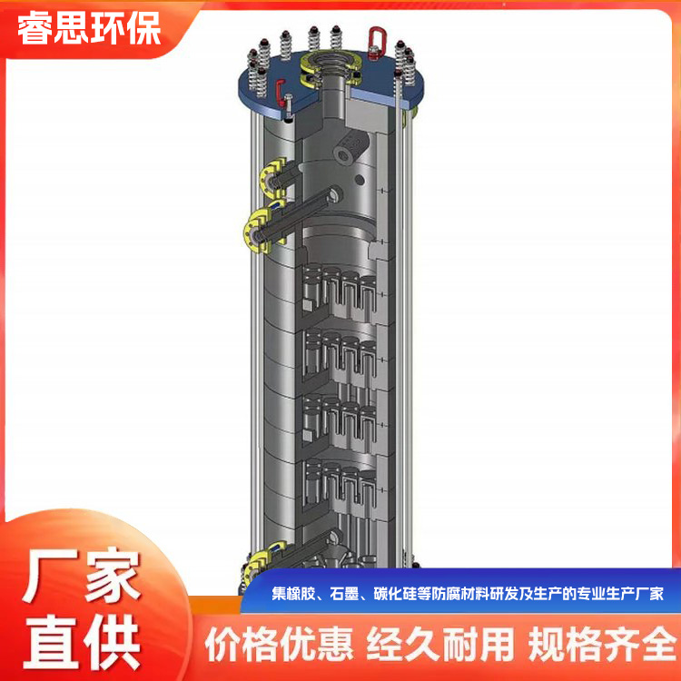
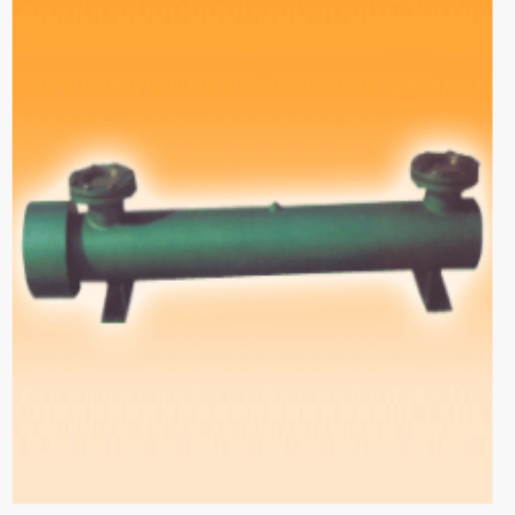
3. Spiral flow guide vanes in a tube-type cooler, ensuring the cooled liquid flows in a spiral, continuous, and uniform manner, overcoming the heat exchange efficiency issues caused by baffle plates.

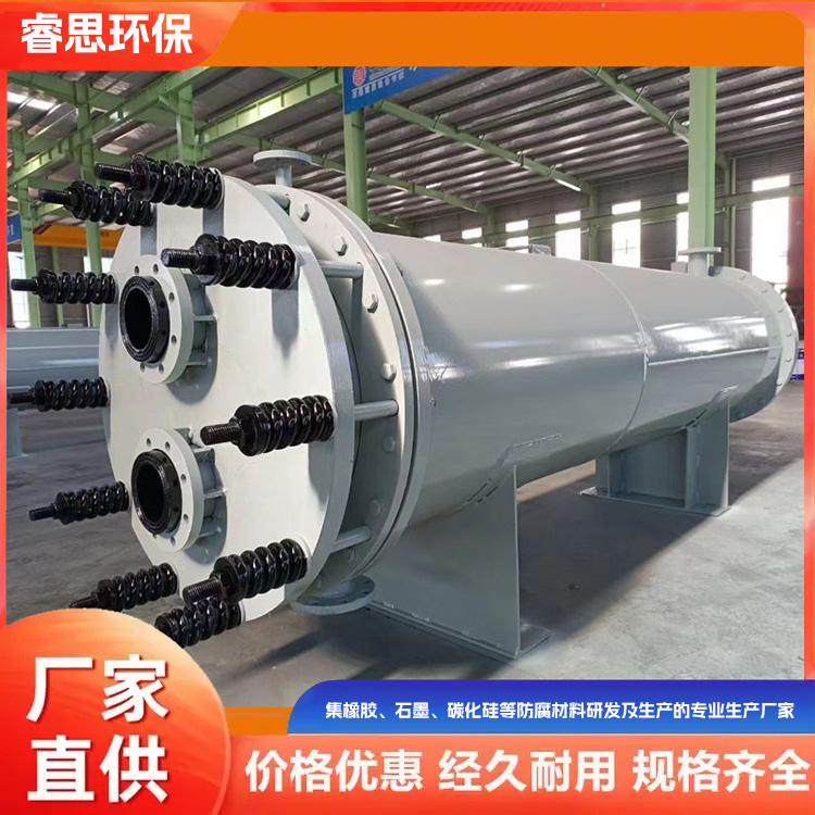
4. Tube-in-tube coolers utilize胀管式封口, overcoming the adverse changes caused by high-temperature welding of materials.
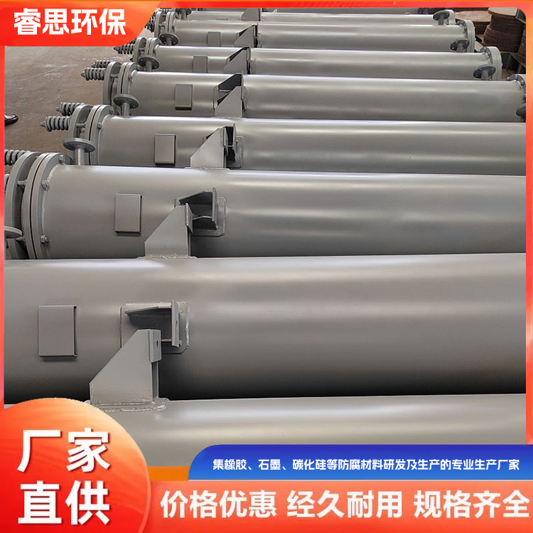
5. The tube-in-tube cooler features excellent structural performance, stable sealing, high heat transfer efficiency, compact structure, and minimal footprint.
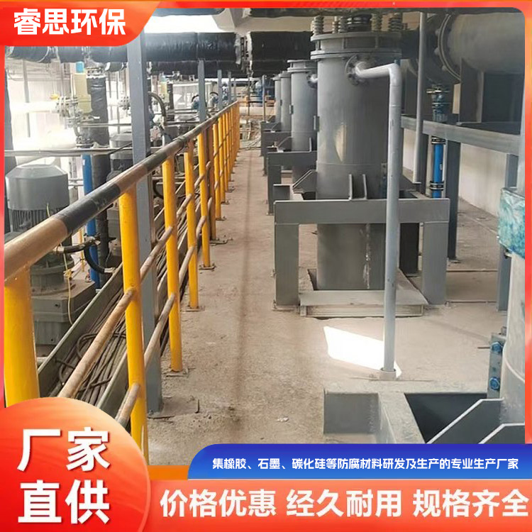
Manual Process: After the filter is connected to the pipeline system, water enters the filter through the lower inlet. As impurities in the water pass through the core, they are trapped on the core due to their larger size compared to the core holes. When they accumulate to a certain quantity, a pressure difference is created between the inlet and outlet. (The pressure difference varies with the filter mesh precision diameter, generally 0.15 Mpa.) Manually open the drain valve to start draining. Rotate the handle, either clockwise or counterclockwise, turning one step every 10-30 seconds. The handle should be fixed at each indentation. The water reverses to flush the impurities stuck to the inner wall surface of the core. Continue until a full rotation is completed, then close the drain valve to finish manual draining.
As per the customer's selectionAutomatic Water FilterOptional pressure difference discharge and timed discharge
1. Differential Pressure Sewage Discharge: Once impurities accumulate to a certain amount, utilize the differential pressure signal between the cooling water's inlet and outlet pipes to backflush and discharge. This is achieved by the electrical contact pressure gauge connecting the control signal, which activates the control mechanism to open the electric sewage valve. The electric reducer operates at a speed of 3-6 rotations per minute, reversing the flow of water to wash away impurities adhering to the inner wall surface of the mesh core. The wastewater is then discharged through the sewage pipeline and valve into the cooling water outlet pipe. The cleaning and discharging process takes approximately 5-10 minutes. In cases where large debris occurs and the filter mesh cannot be properly positioned, the electric device should run in the opposite direction to flush out the debris.
2. Users can set the timing of waste discharge if needed.0-99 hoursThe internal cleaning and drainage time is set to 12 hours, typically draining once every 12 hours. The timing can be adjusted according to the water quality of the power plant. The electric reducer is set to reverse at the designated time to open the drainage valve, followed by a reverse flush and drainage process.