

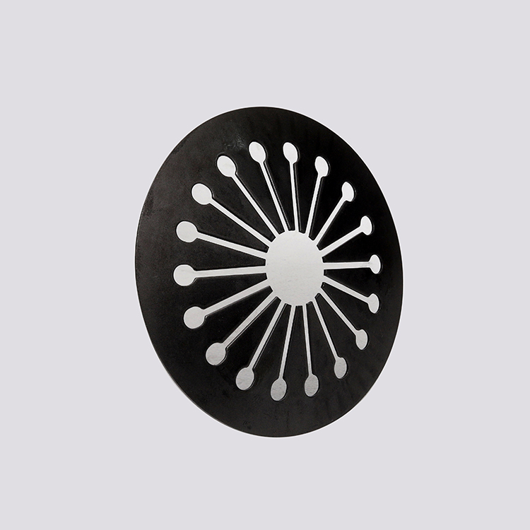


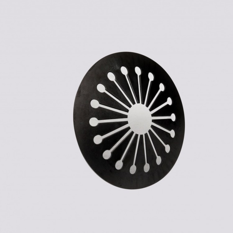

Diaphragm Spring Introduction
Clutch Plate Spring, Technical Conditions
I. Scope
This standard specifies the structural types, technical requirements, testing methods, and inspection rules for diaphragm springs.
This standard applies to diaphragm spring for mechanical clutches (hereinafter referred to as "diaphragm spring"), and the diaphragm spring in dampers is also applicable for reference.
II. Normative References
The following documents are essential for the application of this document. For referenced documents with dates, only the version with the noted date applies to this document. For referenced documents without dates, the latest version (including all amendments) applies to this document.
Method for Determining the Decarburization Layer Depth of Steel according to GB/T 224
GB/T 230.1 Metal Materials Rockwell Hardness Test Part 1: Test Method (Scales A, B, C, D, E, F, G, H, K, N, T)
GB/T 1222 Spring Steel
GB/T 1800.2-2009 Product Geometric Technical Specification (GPS) Limits and Fits Part 2: Standard Tolerance Grades and Hole and Shaft Limit Deviation Tables
GB/T 1972 Disc Spring
GB/T 3279 Hot-Rolled Steel Sheets for Springs
YB/T 5058 Cold-Rolled Spring Steel and Tool Steel Strip
III. Parameter Names, Codes, and Units
Parameter names, codes, and units are listed in Table 1.
Table 1: Parameter Name, Code, and Unit
Parameter Name | Code | Unit |
Diaphragm spring outer diameter | D | mm |
Diaphragm Spring Bore | d | |
Inner diameter of the sealed ring in the diaphragm spring | Dm | |
Diaphragm spring thickness | t | |
Inner cone height of the sealed ring part in diaphragm spring | y | |
Free height of the diaphragm spring | H。 | |
Large deformation of diaphragm spring (inner cone height) | Smax(Smax=Ho-t) | |
Separation refers to the small end width | b1 | |
Separation refers to the width of the window hole slot | b2 | |
Inner radius of the sealed ring in diaphragm spring | r | |
Outer radius of the sealed ring section in the diaphragm spring | R | |
Deformation amount | S | mm |
Deflection amount of the enclosed ring section in diaphragm springs | Is | |
Deflection amount of the tongue part in the diaphragm spring | S2 | |
Separation Index (Number of Tongue Blades) | Z | |
Workload | F | N |
Section 4: Structural Style
4.1Diaphragm spring structure type
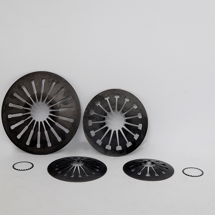
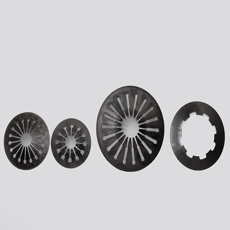
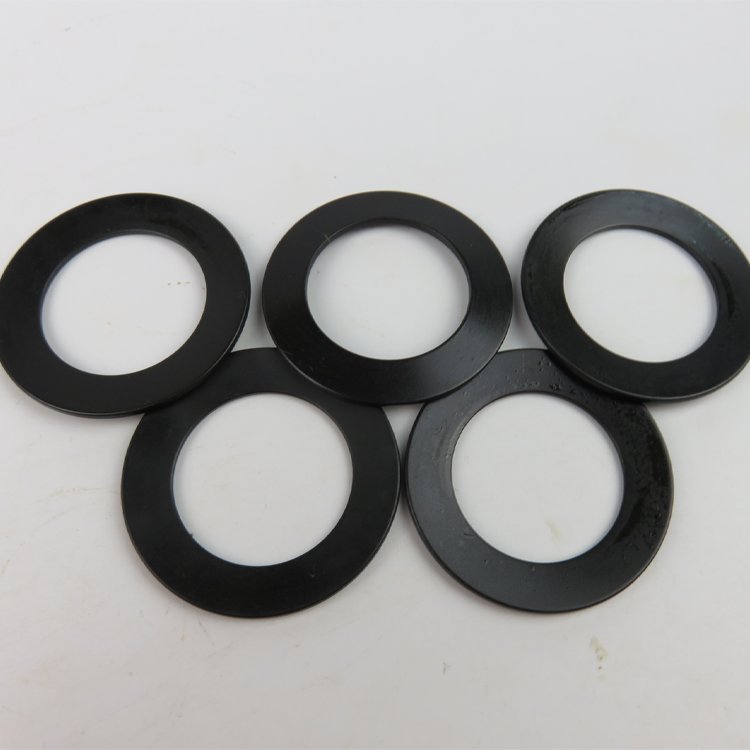
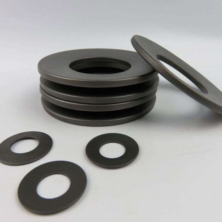
The diaphragm spring structure is as shown in Figure 1.
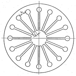

Figure 1: Diaphragm Spring
Section 6: Technical Requirements
6.1 Materials
6.1.1 Material
The material for diaphragm springs is generally 50CrVA or 60Si2MnA, which should comply with the specifications of GB/T 1222 for chemical composition and physical properties; if other materials are used, they can be agreed upon by both parties.
6.1.2 Requirements
The steel strip used for diaphragm springs should comply with the provisions of YB/T 5058, or with GB/T 3279.
6.1.3 Inspection
Materials must be accompanied by a quality assurance certificate from the manufacturer and must pass a re-inspection before use.
6.2 Dimensional Tolerance Limit
6.2.1 Thickness
The allowable deviation of the thickness "t" of the diaphragm spring should comply with the specifications in Table 2. In cases of special requirements, the allowable deviation of thickness "t" shall be agreed upon by both the supplier and the buyer.
Table 2: Maximum Deviation for Thickness tDifference (in millimeters)
Thickness t | Absolute Deviation |
0.5~1.0 | +0.02 -0.03 |
>1.0~2.3 | +0.03 -0.05 |
>2.3~3.0 | +0.04 -0.05 |
>3.0~4.0 | ±0.05 |
6.2.2 Free Height
The allowable deviation for the free height of the diaphragm spring should comply with the specifications in Table 3. Under the assurance of the characteristic requirements, the free height may be appropriately adjusted during manufacturing, but the tolerance value remains unchanged.。
Table 3: Maximum Allowable Deviation of Free Height (in millimeters)
Free Height H. | Ultimate deviation |
<10 | +0.20 -0.10 |
>10~20 | +0.20 -0.20 |
>20~50 | +0.10 -0.50 |
>50~100 | ±1.50 |
6.2.3 Diameter
The inner and outer diameter tolerances of the diaphragm spring are in accordance with the H13 and h13 grades as specified in GB/T 1800.2-2009.
6.3 Flatness
The flatness tolerance of the bottom surface of the diaphragm spring's sealed section should be 0.25mm, and the arc length of the non-contact surface should not exceed 1/3 of the circumference.
6.4 Coaxiality
The coaxial tolerance of diaphragm springs should comply with the specifications in Table 4.
Table 4: Axial Tolerance (in millimeters)
Outer Diameter: D | 30~50 | >50~125 | >125~250 | >250~500 |
Coaxiality tolerance | 0.2 | 0.25 | 0.3 | 0.4 |
6.5 Load Characteristic Limit Deviation
The membrane spring working area characteristics are required based on user needs, but the load deviation at the working point is within -10% to 20%.
6.6 Heat Treatment
The diaphragm spring must be quenched and tempered, and the number of quenching cycles should not exceed two times.
6.7 Hardness
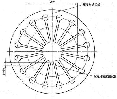
The hardness value of the sealed portion of the spring diaphragm after tempering should be selected within the range of 71.5HRA to 76.8HRA, and the hardness tolerance of a single spring diaphragm should be within ±2HRA.
Surface hardness values for the separated finger tip section (with a maximum diameter of ø70mm) must be above 79HRA, with a depth greater than 0.5mm. A hardness transition zone is permissible between the separated finger tip section and the sealed part, but the minimum hardness in the transition zone should not be less than 68.9HRA.
6.8 Decarburization Depth
The heat-treated diaphragm spring should have a single-sided decarburization layer depth not exceeding 1% of its thickness, and the maximum depth should not exceed 0.05mm.
6.9 High-pressure treatment
Blade springs should be subjected to high-pressure treatment using a load of not less than twice the value of s = 0.75h, for a duration of at least 12 hours, or undergo short-duration compression with a minimum of 5 compression cycles.
6.10 Surface Quality
The surface of the diaphragm spring should be free from burrs, cracks, and any defects harmful to use.
6.11 Surface Corrosion Treatment
Diaphragm springs are typically soaked in anti-rust oil after shot blasting, and can also be treated with oxidation, phosphatization, electro-phoresis, etc. according to customer requirements. Diaphragm springs are not suitable for electroplating treatment.
6.12 Fatigue Life
When fatigue life requirements are specified, the number of fatigue life cycles can be agreed upon by both parties.
Section 7: Testing Methods
7.1 Dimensions and Geometric Tolerance
7.1.1 Thickness
The thickness of the diaphragm spring is measured at least three points along the circumference at both the inner and outer diameters using a micrometer, and the largest value is taken.
7.1.2 Diameter
The diameter of the diaphragm spring is measured using a micrometer with a graduation value not exceeding 0.02mm. At least three measurements are taken at different positions along the circumference, with the outer diameter being the largest value and the inner diameter being the smallest value.
7.1.3 Free Height
The free height of the diaphragm spring should be measured on a grade 2 flatness plate using a depth micrometer with a graduation value of less than or equal to 0.02mm. At least three measurements should be taken at different positions along the circumference, and the maximum value should be taken.
7.1.4 Flatness
Place the diaphragm spring on a secondary precision flat plate, measure the diaphragm spring plane gap at a load of s=0.75ho under 2% load, and take the largest gap value. The maximum load should not exceed 300N, as shown in Figure 3.
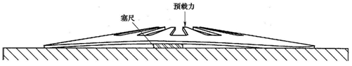
Figure 3: Diagram illustrating flatness
7.1.5 Axial alignment
Place the diaphragm spring on a second-class precision flat plate, measure its diaphragm spring width with a caliper having a least count of 0.02mm or less, as shown in Figure 4. Measure at least three different positions, calculate the difference between the maximum measured value and the theoretical value; this difference is the coaxiality error.
Axiality error can also be agreed upon by both parties for measurement using a converted fixture.
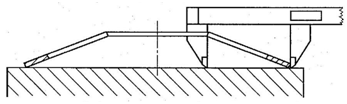
Figure 4: Coaxiality Error Measurement
7.2 Load Characteristics
The load of the diaphragm spring is tested on a machine with accuracy not less than 1%, measuring its load when loaded to the required deformation amount. Lubricant must be used during the test. The hardness of the upper and lower end plates for measuring the load characteristics of the diaphragm spring must be above 52HRC, and the surface roughness Rz must be less than 1.6μm.
7.3 Hardness
The hardness test of diaphragm springs is conducted according to GB/T 230.1 specifications. The indentation should be between the outer diameter of the diaphragm spring and the window, with 4 points marked per piece, the first point being disregarded, and the average of the last three points taken. The separation finger hardness test should be performed within a range of 2mm to 10mm below the finger tip (see Figure 5 of this standard); the method is the same as above.