


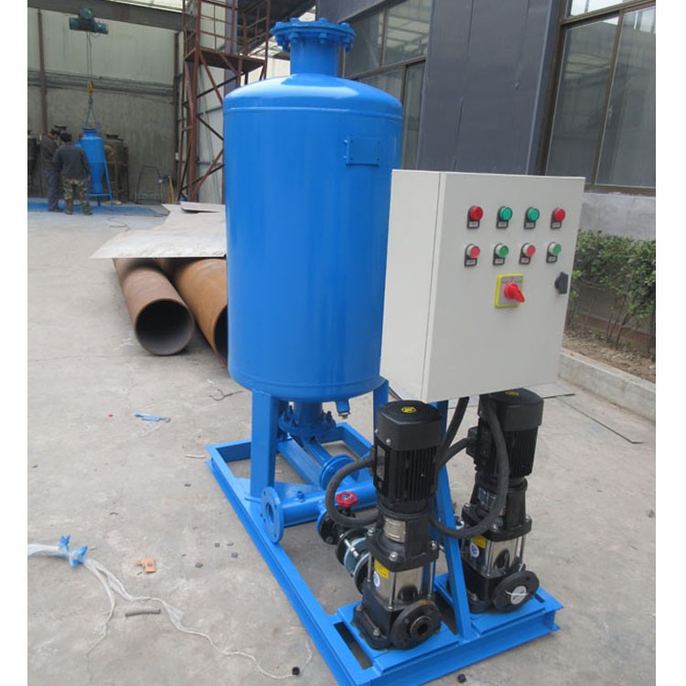


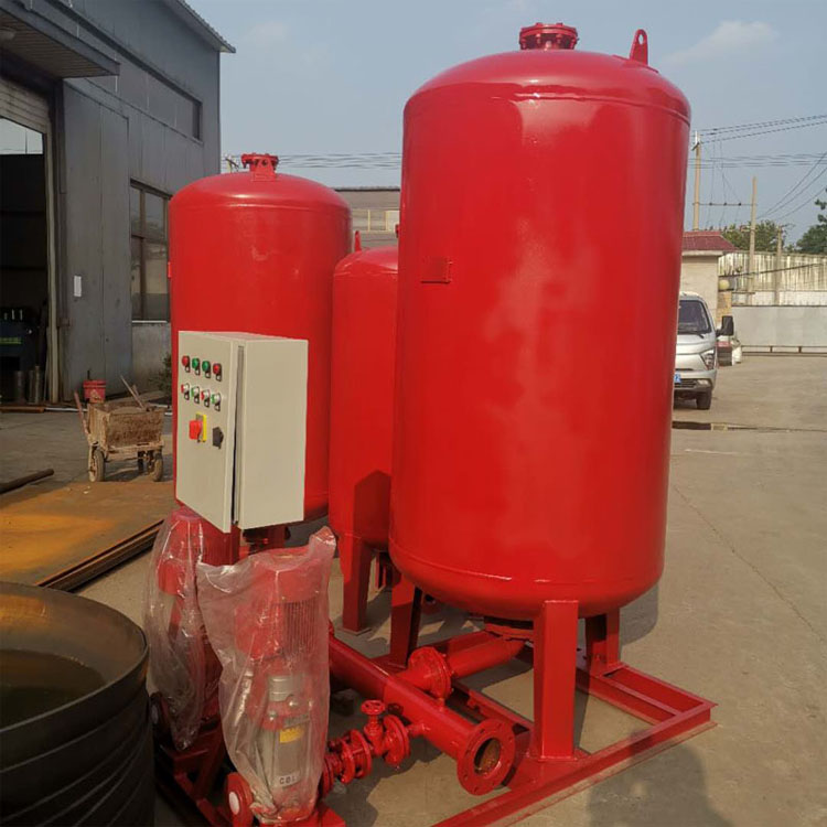

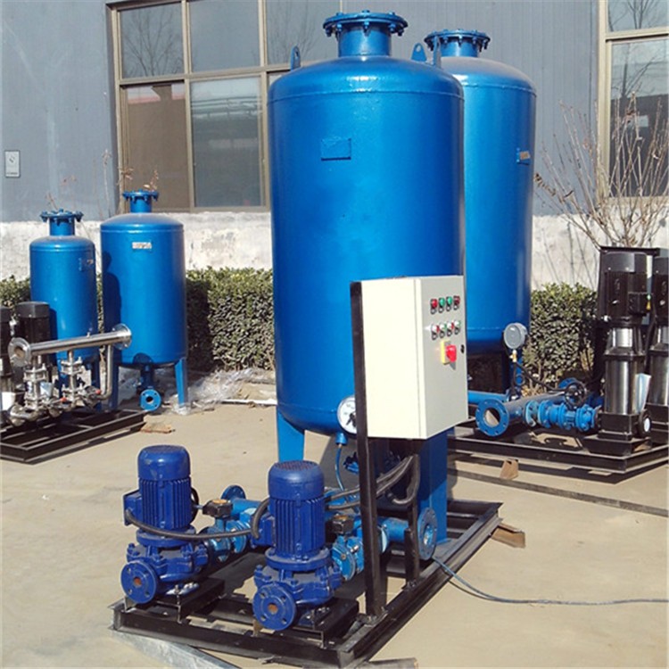
Atmospheric pressure constant-pressure water supply and drainage units, commonly used water supply and drainage equipment in air conditioning systems, serve the functions of maintaining stable pressure and replenishing water. They are widely employed in underground air conditioning rooms, large circulating water pipelines, thermal insulation systems, ground-source heat pumps, and other scenarios. They can also be used in areas such as subway stations, skyscrapers, airports, hospitals, and ice rinks.
Principle of Atmospheric Pressure Constant Pressure Water Supply System:
Based on the scientific principles of pressure and hydraulic expansion, at a constant temperature, the product of pressure and volume of a mass of gas remains constant. As the constant pressure water supply pump operates, while water is supplied to the water distribution network, excess water enters the pressure water tank. The water chamber expands, compressing the tank's gas, which reduces the gas chamber volume. The tank's pressure increases accordingly. When the pressure reaches the high working pressure P2, the electrical control cabinet cuts off the pump's power, stopping the pump. At this point, the compressed gas within the tank is used to send stored water into the water distribution network, reducing the water chamber and expanding the gas chamber, thereby lowering the tank's pressure. When the pressure drops to the working pressure P1, the electrical control cabinet reconnects the pump's power, restarting the pump. This cycle repeats continuously, ensuring a stable water pressure and supplementing the system medium.
Advantages of Atmospheric Pressure Constant Pressure Water Supply System:
1. Fully tested before shipment, available for manual/automatic control
2. Carefully selected brand accessories (such as Southern Pumps), with high water replenishment efficiency
3. Flanges and other connecting parts are made of 304 stainless steel.
4. A wide variety of models available, covering most of the department's needs.
5. Excellent sealing performance: The tank is a sealed unit, with minimal contact between air and water, ensuring water quality remains uncontaminated.
6. Performance: The system has been fully tested before leaving the factory.
7. Easy Installation: Simply connect the in/out water and drainage pipes, perform a basic adjustment, and the unit is ready for use; no on-site fabrication required.
8. High-precision sensors that reduce the frequency of pump startups, saving energy and electricity
Atmospheric pressure pressure-maintenance water-supply system selection:
The system selection primarily includes the following three aspects: the selection of the water replenishment pump, the selection of the pressure tank, and the system's water capacity.
1. Selection of water pump:
a. The lift system's pressure at the make-up water point is 30~50 kPa higher than the head ratio.
b. The total hourly flow should be 5 times the system's water capacity.
c. When the system is large, it is advisable to set up two pumps, using one normally and running both simultaneously during initial filling or accident replenishment (typically two make-up pumps are set up).
2. System Water Capacity:
The hourly leakage rate of the recirculating water system should be calculated based on 1% of the system's water capacity.
Cooling water systems that supply cooling and heating with air conditioners can be estimated according to Table 1. Larger values should be chosen if the outdoor piping is longer.
3. Pressure Vessel Selection
The volume of the pressure tank should be determined according to the following formula:
V≥Vmin=(β*Vt)/(1-α1)
Equation: V = Actual Total Volume of the Pressure Vessel (L)
Vmin — Small Pressure Vessel Volume (L)
Vt – Adjusted Volume (L), should not be less than 3 minutes of normal operation water supply pump flow rate (when using variable frequency pumps, the water supply pump flow rate mentioned above can be determined as 1/3 to 1/4 of the water supply pump flow rate at rated speed)
Beta volume correction factor: 1.05 for diaphragm-type air pressure vessels.
α1-Pressure Ratio, α1 = (P1 + 100) / (P2 + 100), where P1 and P2 are the startup and shutdown pressures of the feedwater pump (gauge pressure in kPa). The value should be determined by considering factors such as the pressure vessel capacity and the system's high operating pressure. It is recommended to be between 0.65 and 0.85.
Installation Note: Atmospheric Pressure Constant Pressure Water Supply Unit
1. This unit should be installed in a location that is protected from frost, with good drainage, and out of direct sunlight, and should be mounted vertically.
2. Ensure the basic drum is positioned horizontally and the control unit is below the basic drum.
3. The base drum is equipped with a weighing sensor system, so the base feet of the drum cannot be anchored to the ground. Otherwise, the weighing sensor will not operate properly, and ensure there are no obstructions in the vertical direction of the drum.
4. No debris should be placed on the basic drum to avoid misleading the weighing system signal.
5. To ensure the accuracy of level weighing, the basic drum and control unit, as well as the basic drum and the first sequential drum BI, must be connected using hoses.
6. Water replenishment pipelines require the installation of filters to prevent impurities from clogging.
7. When the pipeline length exceeds 10M, the pipeline diameter should not be less than DN32.
Ensure the pipeline for expansion is clear, without the need for excessive valves.


