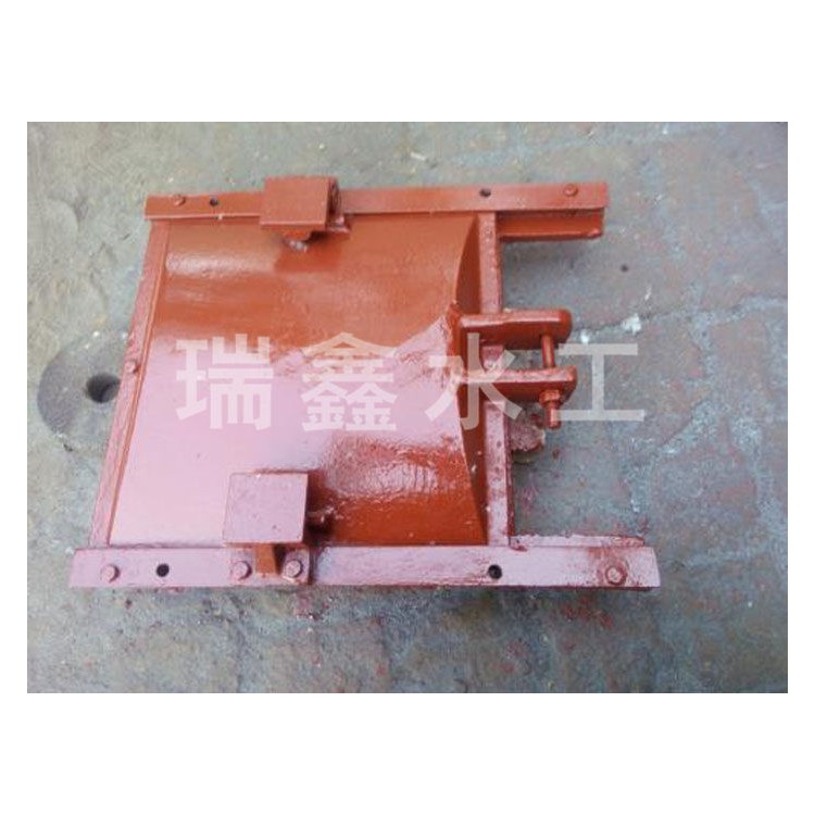


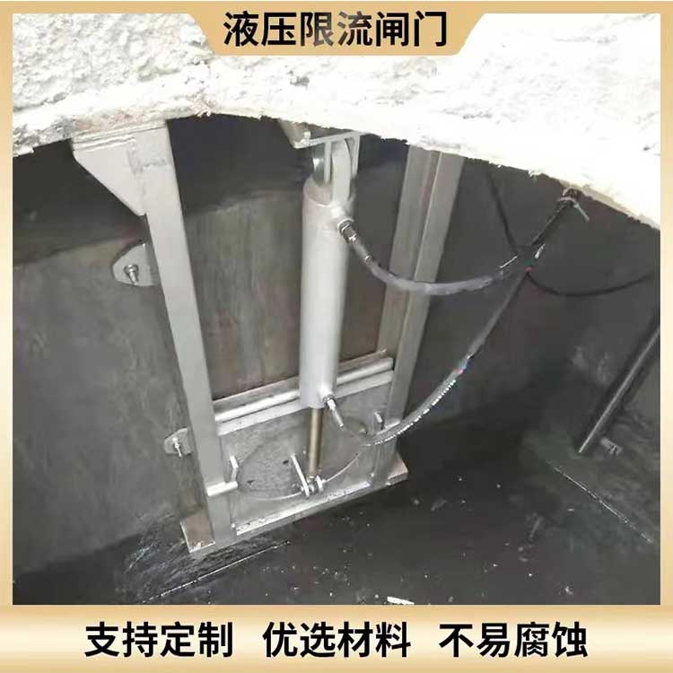
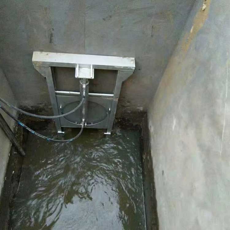
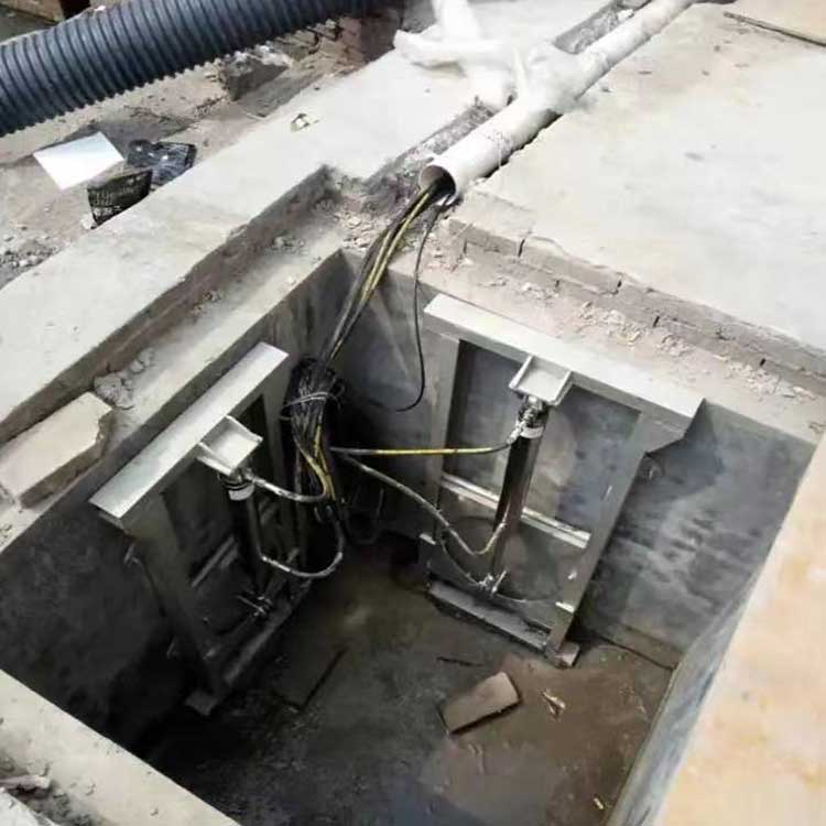
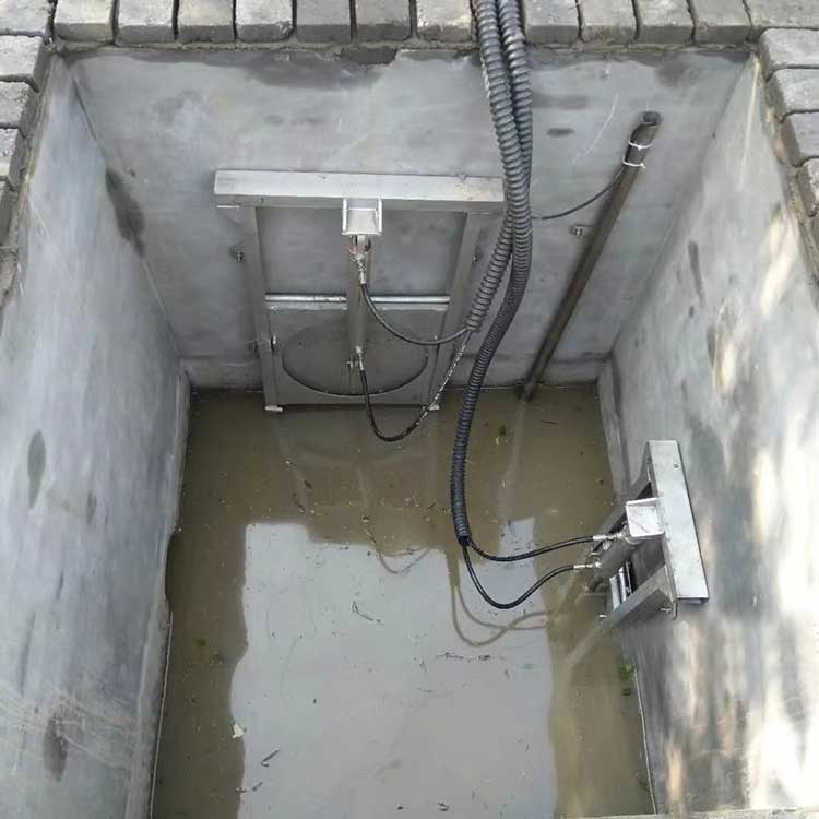


Irrigation gate for paddy fields, characterized by: the bracket (4) is equipped with a motor (5), a linkage mechanism (6), and a stroke switch (7). The linkage mechanism (6) consists of a first linkage (61) and a second linkage (62). One end of the first linkage (61) is fitted over the output shaft of the motor (5), and the two ends of the second linkage (62) are pivotally connected to the ends of the first linkage (61) and the force arm (8). The motor (5) and the stroke switch (7) are fixed to the bracket 4. The lower surface of the stroke switch (7) is equipped with a horizontal position stop switch (71), and the inner surface of the stroke switch (7) is fitted with a vertical position stop switch (72).
Close gate: Start the motor, which rotates the three-link mechanism. The linkage drives the arm to lift the free end of the gate above the water level. When the free end of the gate is horizontal, the arm contacts the horizontal position of the stroke switch, stopping the motor. The free end of the gate remains above the water level without movement. At this point, the gate is closed, preventing water from flowing from the bellows hose into the rigid conduit, thus stopping it from reaching the next field.
3. Open Gate: Start the motor, which rotates the linkage mechanism in the same direction. The free end of the linkage mechanism, attached to the armature gate, is lowered, placing the gate's free end in a vertical position with the ground. At this point, the armature strikes the vertical position of the stroke switch, stopping the motor; the free end of the gate is submerged under the water surface without movement. Consequently, the gate is open, allowing the water channel's flow to enter the rigid conduit and then proceed to the next rice field.